Create successful ePaper yourself
Turn your PDF publications into a flip-book with our unique Google optimized e-Paper software.
Manual<br />
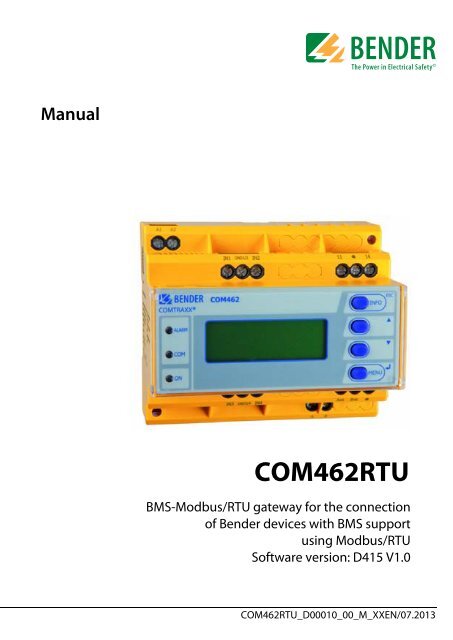
<strong>COM462RTU</strong><br />
BMS-Modbus/RTU gateway for the connection<br />
of <strong>Bender</strong> devices with BMS support<br />
using Modbus/RTU<br />
Software version: D415 V1.0<br />
<strong>COM462RTU</strong>_D00010_00_M_XXEN/07.2013
<strong>Bender</strong> GmbH & Co. KG<br />
Londorfer Str. 65 • 35305 Grünberg • Germany<br />
Postfach 1161 • 35301 Grünberg • Germany<br />
Tel.: +49 6401 807-0<br />
Fax: +49 6401 807-259<br />
E-Mail: info@bender-de.com<br />
Web: http://www.bender-de.com<br />
© <strong>Bender</strong> GmbH & Co. KG<br />
All rights reserved.<br />
Reprinting only with permission<br />
of the publisher.<br />
Subject to change!
Table of Contents<br />
1. Making effective use of this document ....................................................... 7<br />
1.1 How to use this manual ................................................................................. 7<br />
1.2 Overview of chapters ...................................................................................... 7<br />
1.3 Quick reference guide .................................................................................... 8<br />
2. Safety instructions ........................................................................................... 9<br />
2.1 Work activities on electrical installations ................................................ 9<br />
2.2 Intended use ...................................................................................................... 9<br />
2.3 Address setting and termination ............................................................. 10<br />
3. Product description ....................................................................................... 11<br />
3.1 Scope of delivery ........................................................................................... 11<br />
3.2 Short description ........................................................................................... 11<br />
3.3 Properties ......................................................................................................... 11<br />
3.4 Possible applications ................................................................................... 11<br />
3.5 Details about the Modbus RTU ................................................................ 12<br />
4. Installation, connection and commissioning ........................................... 13<br />
4.1 Preliminary considerations ........................................................................ 13<br />
4.2 <strong>COM462RTU</strong> on the internal BMS bus ................................................... 14<br />
4.3 Installing the device ..................................................................................... 15<br />
4.4 Connecting the device ................................................................................ 16<br />
4.5 Commissioning .............................................................................................. 18<br />
5. BMS-Modbus/RTU gateway <strong>COM462RTU</strong> ................................................. 19<br />
5.1 Display and operating elements ............................................................. 19<br />
5.1.1 Automatic contrast setting for the display .......................................... 20<br />
5.1.2 Display in standard mode .......................................................................... 20<br />
5.1.3 Display in menu mode ................................................................................ 21<br />
5.2 Factory setting ............................................................................................... 21<br />
<strong>COM462RTU</strong>_D00010_00_M_XXEN/07.2013<br />
3
Table of Contents<br />
5.3 Menu 1: Settings on the device ................................................................ 22<br />
5.3.1 Operating example: Setting the BMS address .................................... 22<br />
5.3.2 Menu 2: Display INFO list ............................................................................ 24<br />
6. Data access using Modbus/RTU protocol ................................................. 25<br />
6.1 Exception code ............................................................................................... 25<br />
6.2 Modbus requests ........................................................................................... 26<br />
6.3 Modbus responses ........................................................................................ 26<br />
6.4 Structure of the exception code .............................................................. 27<br />
6.5 Modbus address structure for BMS devices ......................................... 27<br />
7. Modbus process image in the memory of the <strong>COM462RTU</strong> ................. 29<br />
7.1 Requesting data ............................................................................................. 29<br />
7.1.1 Modbus function code ................................................................................ 29<br />
7.1.2 How are memory areas organised ........................................................ 29<br />
7.2 Memory scheme of the process image ................................................ 30<br />
7.2.1 BMS device address assignment on the Modbus .............................. 30<br />
7.2.2 Memory scheme of an individual BMS device .................................... 31<br />
7.2.3 Device type ...................................................................................................... 33<br />
7.2.4 Timestamp ....................................................................................................... 34<br />
7.2.5 C = Common alarm und D = Device lost (device failure) ................ 34<br />
7.2.6 Channels 1 to 32 with analogue and/or digital values .................... 35<br />
7.2.6.1 Float = Floating point value of the BMS channels .................... 35<br />
7.2.6.2 A&T = Alarm type and test type (internal/external) ................. 36<br />
7.2.6.3 R&U = Range and unit ......................................................................... 37<br />
7.2.6.4 Channel description ............................................................................. 39<br />
7.2.6.5 Channel 33 to 64 ................................................................................... 40<br />
7.3 Reference data records of the process image ..................................... 41<br />
7.3.1 Address assignment of the reference data record ............................ 41<br />
7.3.2 Reference value on channel 1 ................................................................... 42<br />
7.3.3 Reference value on channel 2 ................................................................... 43<br />
7.3.4 Explanation of how to access floating point values ......................... 43<br />
7.4 Channel descriptions for the process image ....................................... 45<br />
4 <strong>COM462RTU</strong>_D00010_00_M_XXEN/07.2013
Table of Contents<br />
7.5 Modbus control commands ...................................................................... 57<br />
8. Technical data ................................................................................................. 61<br />
8.1 Tabular data .................................................................................................... 61<br />
8.2 Dimension diagram ...................................................................................... 63<br />
8.3 Standards, approvals, certifications ........................................................ 63<br />
8.4 Ordering information .................................................................................. 64<br />
9. Troubleshooting ............................................................................................ 65<br />
9.1 Damage in transit .......................................................................................... 65<br />
9.2 Malfunctions ................................................................................................... 65<br />
9.2.1 What should be checked .......................................................................... 65<br />
9.2.2 Where do you get help .............................................................................. 66<br />
INDEX ..................................................................................................................... 67<br />
<strong>COM462RTU</strong>_D00010_00_M_XXEN/07.2013<br />
5
1. Making effective use of this document<br />
1.1 How to use this manual<br />
This operating manual will concern qualified experts in electrical<br />
engineering and communication technology!<br />
To make it easier for you to understand and revisit certain sections of text and<br />
instructions in the manual, we have used symbols to identify important instructions<br />
and information. The meaning of these symbols is explained below:<br />
Information which is designed to help you make the best<br />
use of the product is highlighted with the information<br />
symbol<br />
Information which refers to hazards is highlighted with<br />
the warning symbol<br />
1.2 Overview of chapters<br />
• Making effective use of this document:<br />
This chapter gives you instructions on how to use this documentation<br />
• Safety instructions<br />
This chapter describes the dangers during installation and when operating<br />
the device<br />
• Product description:<br />
This chapter describes the scope of delivery and features of the product<br />
<strong>COM462RTU</strong>_D00010_00_M_XXEN/07.2013<br />
7
Making effective use of this document<br />
• Installation, connection and commissioning:<br />
This chapter shows the steps to take up to commissioning<br />
• BMS-Modbus/RTU gateway <strong>COM462RTU</strong>:<br />
This chapter describes the display and operating elements<br />
• Data access using Modbus/RTU protocol:<br />
Describes how to send requests to the Modbus/RTU slave of the<br />
<strong>COM462RTU</strong> and how the responses are to be interpreted<br />
• Modbus process image in the <strong>COM462RTU</strong>'s memory<br />
In this chapter, the representation of BMS data on Modbus/RTU structures<br />
is described in detail<br />
• Technical data:<br />
In addition to the technical data you will find here ordering data<br />
• Troubleshooting:<br />
This chapter offers service and support in case of malfunction. In addition<br />
you will also find here information on our Technical Service<br />
department<br />
• INDEX:<br />
The key word index assists you in finding the term you are searching<br />
for.<br />
1.3 Quick reference guide<br />
Connection of the <strong>COM462RTU</strong><br />
If you are familiar with the installation and connection of electrical devices,<br />
particularly with Modbus/RTU, you can start right away with the wiring diagram<br />
on page 16.<br />
It may also be helpful to refer to the block diagrams representing an application<br />
example with an internal BMS bus on page 14.<br />
Using the Modbus/RTU functions<br />
Information about this field can be found as of page 25.<br />
8 <strong>COM462RTU</strong>_D00010_00_M_XXEN/07.2013
2. Safety instructions<br />
2.1 Work activities on electrical installations<br />
• Only skilled persons are permitted to carry out the work necessary to<br />
install, commission and run a device or system.<br />
• Compliance with applicable regulations governing work on electrical<br />
installations, and with the regulations derived from and associated<br />
with them, is mandatory. EN 50110 is of particular importance in this<br />
regard.<br />
Any work on electrical installations which is not carried<br />
out properly can lead to death and injury!<br />
• If the device is being used in a location outside the Federal Republic of<br />
Germany, the applicable local standards and regulations must be complied<br />
with. European standard EN 50110 can be used as a guide.<br />
2.2 Intended use<br />
The BMS-Modbus/RTU gateway <strong>COM462RTU</strong> connects the serial <strong>Bender</strong> BMS<br />
bus to the serial Modbus/RTU. The gateway converts alarms, measured values<br />
and statuses from the BMS bus to Modbus/RTU. Control commands can be<br />
converted from Modbus/RTU to BMS bus.<br />
This allows connection to Modbus networks. The gateway is operated on the<br />
internal BMS bus.<br />
<strong>COM462RTU</strong>_D00010_00_M_XXEN/07.2013<br />
9
Safety instructions<br />
2.3 Address setting and termination<br />
In order to ensure proper functioning of the BMS/Modbus/RTU gateway<br />
<strong>COM462RTU</strong>, correct address assignment and termination of the BMS bus and<br />
the Modbus/RTU is of utmost importance.<br />
Assigning addresses that are already used by existing devices<br />
in the BMS or Modbus/RTU networks concerned<br />
may cause serious malfunctions.<br />
Ensure correct address setting and termination of the <strong>COM462RTU</strong>. For details<br />
refer to “Commissioning” on page 18.<br />
Interface on the Modbus/RTU side<br />
The <strong>COM462RTU</strong> is always operated as slave on the Modbus/RTU<br />
side. Therefore, the <strong>COM462RTU</strong> and its Modbus/RTU<br />
has to be communicated to the Modbus/RTU<br />
master.<br />
Interface on the BMS side<br />
<strong>COM462RTU</strong> can be operated as master or slave.<br />
10 <strong>COM462RTU</strong>_D00010_00_M_XXEN/07.2013
3. Product description<br />
3.1 Scope of delivery<br />
You will receive:<br />
• the <strong>COM462RTU</strong><br />
• an operating manual<br />
3.2 Short description<br />
The BMS-Modbus/RTU gateway <strong>COM462RTU</strong> contains a Modbus/RTU slave<br />
that converts BMS data for a Modbus master.<br />
A setting menu makes it possible to configure the <strong>COM462RTU</strong> using the setting<br />
menu (see “Commissioning” on page 18.).<br />
3.3 Properties<br />
• Setting of address data for the BMS bus and Modbus/RTU and date and<br />
time setting using the internal operating menu.<br />
• Time synchronisation for all BMS bus devices<br />
• Operation on the internal BMS bus<br />
• Modbus/RTU data access to the internal BMS bus, max. 150 BMS<br />
devices<br />
• Commands can be sent from an external application (e.g. visualisation<br />
software) to BMS devices and measured values read.<br />
3.4 Possible applications<br />
• The use of professional visualisation programs by converting BMS data<br />
to Modbus/RTU protocols.<br />
• Observing and analysing <strong>Bender</strong> products that support communication,<br />
such as RCMS, EDS and MEDICS® systems<br />
<strong>COM462RTU</strong>_D00010_00_M_XXEN/07.2013<br />
11
Product description<br />
3.5 Details about the Modbus RTU<br />
The Modbus RTU (Remote Terminal Unit) field bus has been specified by Modicon,<br />
a company under the Schneider Automation brand and made available<br />
to the market license-free.<br />
Modbus uses the serial hardware interface RS-485 and communicates via a<br />
two-wire, twisted copper wire. A transmission rate of 19200 baud is standard.<br />
Key data:<br />
• Master-slave communication<br />
• Up to 32 bus devices per network, or up to 247 bus devices (with<br />
repeater)<br />
• Baud rate between 1200 and 57600 bit/s<br />
• Diagnostics mechanisms<br />
12 <strong>COM462RTU</strong>_D00010_00_M_XXEN/07.2013
4. Installation, connection and commissioning<br />
If you are familiar with the configuration of Modbus/RTU<br />
networks, you can carry out the connection of the<br />
<strong>COM462RTU</strong> by yourself. Otherwise please contact<br />
your EDP administrator!<br />
4.1 Preliminary considerations<br />
1. Have all the questions as regards the installation been answered by the<br />
technician responsible for the installation<br />
2. The device is operated on the internal bus. Is the BMS address to be set<br />
known<br />
If, apart from the <strong>COM462RTU</strong>, an alarm indicator and test combination<br />
MK800 is connected to the internal bus, the <strong>COM462RTU</strong> must not<br />
have the address 1 (master).<br />
You will find more detailed information on the BMS topic, in particular<br />
about the wiring of bus devices, in the separate document "BMS bus".<br />
You can download the document from the download area of the website<br />
www.bender-de.com.<br />
3. Is the Modbus/RTU address to be set known<br />
<strong>COM462RTU</strong>_D00010_00_M_XXEN/07.2013<br />
13
Installation, connection and commissioning<br />
4.2 <strong>COM462RTU</strong> on the internal BMS bus<br />
<strong>Bender</strong> systems such as EDS46x/49x, RCMS46x/49x and MEDICS communicate<br />
with each other via the <strong>Bender</strong> measuring device interface BMS.<br />
The BMS-Modbus/RTU gateway <strong>COM462RTU</strong> provides the coupling between<br />
the BMS bus and Modbus/RTU networks. The following block diagram illustrates<br />
the operation of the gateway in an internal BMS bus.<br />
D+ D- D+ D- D+ D-<br />
D+ D-<br />
<strong>COM462RTU</strong><br />
Fig. 4.1: Block diagram of a coupling between an internal BMS bus<br />
and Modbus/RTU<br />
14 <strong>COM462RTU</strong>_D00010_00_M_XXEN/07.2013
Installation, connection and commissioning<br />
Internal and external BMS bus<br />
The majority of <strong>Bender</strong> devices communicates via the internal<br />
BMS bus.<br />
Individual devices, such as MK800, TM800 or <strong>Bender</strong> panels<br />
can communicate via both the internal BMS bus (BMS<br />
i) and the external BMS bus (BMS e).<br />
The BMS-Modbus/RTU gateway <strong>COM462RTU</strong> can only<br />
communicate via the internal BMS bus (BMS i).<br />
4.3 Installing the device<br />
Possible methods of mounting:<br />
• DIN rail mounting<br />
• Screw mounting with 2 x M4 (dimension diagram on page 63)<br />
When installing the device, please take into consideration<br />
that the device is only to be used in locations that are<br />
protected from unauthorised entry! This can be installation<br />
works in a switchboard cabinet, for example.<br />
<strong>COM462RTU</strong>_D00010_00_M_XXEN/07.2013<br />
15
Installation, connection and commissioning<br />
4.4 Connecting the device<br />
For UL application, the following is to be observed:<br />
– Supply voltage U s see nameplate and ordering information<br />
– Maximum ambient temperature 55°C<br />
– For use in pollution degree 2 environments<br />
– Only 60/75-°C copper wires are to be used<br />
– Tightening torque for terminals 0.5...0.6 Nm<br />
Connect the terminals and sockets on the <strong>COM462RTU</strong> according to the wiring<br />
diagram.<br />
U S<br />
6 A 6 A<br />
A1<br />
A2<br />
A1 A2<br />
IN1 GND IN2<br />
1/2 11 14<br />
IN3<br />
GND<br />
3/4<br />
IN4<br />
A B<br />
AMB BMB<br />
(AMB, BMB)<br />
AMB BMB<br />
BMS-Bus<br />
RS-485<br />
Modbus/RTU<br />
RS-485<br />
16 <strong>COM462RTU</strong>_D00010_00_M_XXEN/07.2013
Installation, connection and commissioning<br />
Terminal<br />
Description<br />
A1, A2 Connection to the supply voltage, 6 A fuse recommended,<br />
two-pole fuses should be used on IT systems.<br />
For UL and CSA applications, it is mandatory to use 5 A fuses<br />
A, B Connection to the BMS bus (internal) with shielded cable<br />
(e.g. J-Y(St)Y 2x0.8)<br />
AMB, BMB<br />
R on/off<br />
(A, B)<br />
Connection Modbus/RTU with shielded cable<br />
(e.g. J-Y(St)Y2x0.8)<br />
Switch for BMS bus termination. When the device is installed<br />
at the end of the bus, set the termination switch to "on".<br />
R on/off<br />
(AMB, BMB)<br />
IN1,<br />
GND1/2,<br />
IN2<br />
Switch for Modbus/RTU termination. When the device is<br />
installed at the end of the bus, set the termination switch to<br />
"on".<br />
Currently has no function (digital inputs)<br />
11, 14 Currently has no function (alarm relay K1)<br />
IN3,<br />
GND3/4,<br />
IN4<br />
Currently has no function (digital inputs)<br />
<strong>COM462RTU</strong>_D00010_00_M_XXEN/07.2013<br />
17
Installation, connection and commissioning<br />
4.5 Commissioning<br />
1. Apply the supply voltage to the <strong>COM462RTU</strong>. The green "ON" LED illuminates.<br />
2. Set language and time.<br />
3. Set the BMS bus. The <strong>COM462RTU</strong> is operated on the internal BMS bus.<br />
4. Set the Modbus/RTU.<br />
For details about the settings refer to the chapter "Menu overview of the functions<br />
adjustable at the device" on page 24.<br />
18 <strong>COM462RTU</strong>_D00010_00_M_XXEN/07.2013
5. BMS-Modbus/RTU gateway <strong>COM462RTU</strong><br />
5.1 Display and operating elements<br />
COMTRAXX®<br />
COM462<br />
4<br />
3<br />
2<br />
1<br />
8<br />
5<br />
6<br />
7<br />
Key<br />
1 "ON“ LED lights when supply voltage is applied<br />
2 "COM“ LED lights when the gateway is responding to BMS requests<br />
3 "ALARM" LED, lights when an internal device error occurs<br />
4 "INFO" button, to query the <strong>COM462RTU</strong> for device-specific information<br />
ESC To exit the menu function without changing parameters<br />
5 "" button: to move up in the menu, to increase the parameter<br />
value<br />
6 "" button: to move down in the menu, to decrease values<br />
7 "MENU" button for starting and exiting the menu<br />
"↵" button to confirm parameter change<br />
8 LC display for standard and menu mode<br />
<strong>COM462RTU</strong>_D00010_00_M_XXEN/07.2013<br />
19
BMS-Modbus/RTU gateway <strong>COM462RTU</strong><br />
5.1.1 Automatic contrast setting for the display<br />
The display contrast control is factory set to an optimum value. In exceptional<br />
cases, it may be necessary to adjust the contrast manually.<br />
Simultaneously press the "ESC" and "↵" buttons. All available contrast modes<br />
are continuously indicated in an infinite loop: minimum contrast, maximum<br />
contrast, no contrast (lasting some seconds), then the same cycle starts again.<br />
If the button "" is additionally pressed, the contrast modes will be displayed<br />
in the opposite direction.<br />
Release the button as soon as the desired level of contrast is reached.<br />
5.1.2 Display in standard mode<br />
Network-related parameters will be indicated.<br />
1<br />
2<br />
3<br />
4<br />
<strong>COM462RTU</strong><br />
Address:1<br />
Modbus:240<br />
22.06.2013 12:34<br />
Key<br />
1 Device type<br />
2 BMS address of the <strong>COM462RTU</strong><br />
3 Modbus address of the <strong>COM462RTU</strong><br />
4 Current date and time<br />
20 <strong>COM462RTU</strong>_D00010_00_M_XXEN/07.2013
BMS-Modbus/RTU gateway <strong>COM462RTU</strong><br />
5.1.3 Display in menu mode<br />
Use the "MENU" button to switch to the Menu mode.<br />
Exit<br />
1. Settings<br />
2. Info<br />
A blinking cursor supports menu navigation.<br />
• You can access the individual menus by means of the "" or "" button.<br />
• Press the "↵" button to confirm the selection of a menu or any setting<br />
you changed.<br />
• To leave the respective menu level or discard a setting which is not<br />
confirmed yet, press the "ESC" button.<br />
Menu mode is exited if no button is pressed for longer<br />
than five minutes.<br />
Menu item Function Page<br />
Exit<br />
Exit menu mode<br />
1. Settings Make the necessary settings for this device 22<br />
2. Info Display information on device type and<br />
firmware versions. The same information as<br />
indicated in the standard mode when<br />
pressing the "INFO" button.<br />
24<br />
5.2 Factory setting<br />
All factory settings you will find in the table on page 22.<br />
<strong>COM462RTU</strong>_D00010_00_M_XXEN/07.2013<br />
21
BMS-Modbus/RTU gateway <strong>COM462RTU</strong><br />
5.3 Menu 1: Settings on the device<br />
The menu is divided into three levels. All menus listed in the table can be<br />
called via the main menu "1. Settings" in the uppermost menu level. All control<br />
buttons are explained on page 19.<br />
5.3.1 Operating example: Setting the BMS address<br />
The example shows the operating principle. All settings are carried out in the<br />
same way.<br />
1. Press the "MENU" button on the <strong>COM462RTU</strong><br />
2. Select "1. Settings" > "1. Interface" > "1. Address". The factory-set BMS<br />
address will be displayed and can be changed now.<br />
3. Modify the addresses using the buttons "" or "".<br />
4. Confirm the modified BMS address with "Enter".<br />
Menu<br />
level 2<br />
Menu<br />
level 3<br />
Factory<br />
setting<br />
Description<br />
1. Interface 1. Address 2 Set the BMS address of <strong>COM462RTU</strong>:<br />
1…99 (internal BMS bus)<br />
2. Interval 2 s Set the cycle time 1…3s for the<br />
sequence:<br />
- Querying alarms in the BMS bus<br />
- Querying new bus devices<br />
- Offering the BMS master function<br />
3. Failure<br />
monitoring<br />
5 Number of BMS bus cycles until a<br />
BMS device failure is signalled. The<br />
setting is only effective when the<br />
<strong>COM462RTU</strong> has the master function<br />
on the BMS bus (address 1).<br />
Adjustable cycles: 1...10<br />
2. Modbus 1. Address 2 Set the Modbus/RTU address for<br />
<strong>COM462RTU</strong>: 2…247<br />
22 <strong>COM462RTU</strong>_D00010_00_M_XXEN/07.2013
BMS-Modbus/RTU gateway <strong>COM462RTU</strong><br />
Menu<br />
level 2<br />
Menu<br />
level 3<br />
Factory<br />
setting<br />
Description<br />
3. Language<br />
2. Baud<br />
rate<br />
19200 Set the baud rate<br />
3. Parity even Set the parity<br />
4. Control off Switch on or switch off the control<br />
commands via Modbus<br />
1. English Deutsch Selection of the operating language<br />
2. Deutsch<br />
3. Français<br />
4. Clock 1. Format d.m.y Date format: m-d-y / d.m.y<br />
2. Date 01.01.2010 Date<br />
3. Time 00:00 Time<br />
4. CEST off Select Central European Summer<br />
Time:<br />
off = Function switched off<br />
DST = Automatic switchover, USA,<br />
CDN<br />
CEST = Automat. switchover, Central<br />
Europe<br />
on = set time zone + 1 h<br />
5. Password<br />
1. Password<br />
000 Enter/change password: 0…999<br />
off Enable/disable password protection<br />
2. Status<br />
for parameter setting via the buttons<br />
of the <strong>COM462RTU</strong><br />
6. Service For authorised <strong>Bender</strong> Service personnel only.<br />
<strong>COM462RTU</strong>_D00010_00_M_XXEN/07.2013<br />
23
BMS-Modbus/RTU gateway <strong>COM462RTU</strong><br />
5.3.2 Menu 2: Display INFO list<br />
Open the "INFO" menu:<br />
• In the standard mode: press the "INFO" button or<br />
• In the menu mode: select function "2. Info".<br />
<strong>COM462RTU</strong><br />
Address:1<br />
Device:B95061022<br />
S:0123456789<br />
This menu displays information about the device and the software. Navigate<br />
in the list using the "" resp. the "" button.<br />
1. Name of the device<br />
2. BMS address<br />
3. Order number<br />
4. Serial number<br />
5. Software version<br />
6. Manufacturer's address<br />
Please have this information to hand if you need to contact us for assistance<br />
by telephone.<br />
24 <strong>COM462RTU</strong>_D00010_00_M_XXEN/07.2013
6. Data access using Modbus/RTU protocol<br />
Request to the <strong>COM462RTU</strong> are sent using the function code 0x03 (read several<br />
registers). The <strong>COM462RTU</strong> generates a function-related response and returns<br />
it.<br />
6.1 Exception code<br />
If a request cannot be answered for whatever reason, the <strong>COM462RTU</strong> sends<br />
a so-called exception code with which possible faults can be narrowed down.<br />
Exception<br />
code<br />
0x01<br />
0x02<br />
0x03<br />
0x04<br />
0x05<br />
0x06<br />
0x08<br />
0x0A<br />
0x0B<br />
Description<br />
Impermissible function<br />
Impermissible data access<br />
Unacceptable data value<br />
Slave device error<br />
Acknowledgement of receipt (answer will be time-delayed)<br />
Request not accepted (repeat request, if necessary)<br />
Memory: Parity Error<br />
Gateway path not available<br />
Gateway error<br />
<strong>COM462RTU</strong>_D00010_00_M_XXEN/07.2013<br />
25
Data access using Modbus/RTU protocol<br />
6.2 Modbus requests<br />
The required words of the process image can be read from the input registers<br />
in the <strong>COM462RTU</strong> using the function code 0x03. For this purpose, the start<br />
address and the number of the registers to be read out have to be entered.<br />
Example:<br />
The Words 0 and 1 are to be read out from the input registers 0x100 and<br />
0x101.<br />
Byte Name Example<br />
Byte 0 Address 0x02<br />
Byte 1 Function 0x03<br />
Byte 2, 3 Start address 0x01 00<br />
Byte 4, 5 Number of registers 0x00 02<br />
Byte 6, 7 CRC16 0x12 34<br />
6.3 Modbus responses<br />
The responses consist of 2 bytes per register.<br />
Byte Name Example<br />
Byte 0 Address 0x02<br />
Byte 1 Function 0x03<br />
Byte 2 Number of data bytes 0x04<br />
Byte 3…6 Information 0xAB CD 01 23<br />
Byte 7, 8 CRC16 0x12 34<br />
26 <strong>COM462RTU</strong>_D00010_00_M_XXEN/07.2013
Data access using Modbus/RTU protocol<br />
6.4 Structure of the exception code<br />
Byte Name Example<br />
Byte 0 Address 0x02<br />
Byte 1 Code + 0x80 0x83<br />
Byte 2 Data 0x04<br />
Byte 3, 4 CRC16 0x12 34<br />
6.5 Modbus address structure for BMS devices<br />
Function<br />
Address range<br />
Number of<br />
bytes<br />
Number of<br />
Words<br />
Device type 0x00…0x09 20 bytes 10 Words<br />
Timestamp 0x0A…0x0D 8 bytes 4 Words<br />
Common alarm<br />
0x0E<br />
(High byte)<br />
1 byte 0.5 Words<br />
No BMS bus connection<br />
0x0E<br />
(Low byte)<br />
1 byte 0.5 Words<br />
Unused 0x0F 2 bytes 1 Word<br />
Channel 1…32 0x10…0x8F 32 x 8 bytes 128 Words<br />
Alarm and test<br />
Channel 33…64<br />
0x90…0xFC 218 x 8 bytes 109 Words<br />
<strong>COM462RTU</strong>_D00010_00_M_XXEN/07.2013<br />
27
Data access using Modbus/RTU protocol<br />
28 <strong>COM462RTU</strong>_D00010_00_M_XXEN/07.2013
7. Modbus process image in the memory of the<br />
<strong>COM462RTU</strong><br />
The device holds a process image in the memory. It represents the current statuses<br />
and values of up to 150 BMS devices for each monitored internal BMS bus.<br />
7.1 Requesting data<br />
7.1.1 Modbus function code<br />
The memory in the <strong>COM462RTU</strong> can be read using the Modbus function 0x03<br />
(read several registers). The size of the data volume to be queried depends on<br />
the number of bytes selected in the Modbus client being used. Up to 125<br />
Words (0x7D) can be read by one single request.<br />
An individual addressable byte, such as the set bit of a stored common alarm,<br />
can also be read out.<br />
7.1.2 How are memory areas organised<br />
Memory utilisation<br />
Start address<br />
End of the<br />
memory area<br />
Size of the<br />
memory area<br />
Reference values<br />
for testing purposes<br />
0x0000 0x00FF 0x0100<br />
Process image 0x0100 0x95FF 0x9500<br />
Unused 0x96FF 0xFFFF 0x6900<br />
In some Modbus clients, an offset of 1 must be added to<br />
the register addresses. Example: Process image start address<br />
= 0x0101.<br />
<strong>COM462RTU</strong>_D00010_00_M_XXEN/07.2013<br />
29
Modbus process image in the memory of the <strong>COM462RTU</strong><br />
The assignment of the memory addresses and the associated memory content<br />
is described below.<br />
7.2 Memory scheme of the process image<br />
7.2.1 BMS device address assignment on the Modbus<br />
As illustrated in the table, the Modbus start address for the respective process<br />
image is derived from the BMS device address. 256 (0x100) Words or 512 bytes<br />
are reserved for each BMS device. They contain all the information requested<br />
and transmitted from the bus.<br />
Modbus address ranges of the process images in the<br />
memory<br />
BMS<br />
device<br />
address<br />
HiByte<br />
Word<br />
LoByte<br />
00 … FF<br />
1 0x01 Device 1<br />
2 0x02 Device 2<br />
3 0x03 Device 3<br />
… … …<br />
32 0x20 Device 32<br />
… … …<br />
150 0x96 Device 150<br />
Tab. 7.1: Modbus start address for each BMS device<br />
for which a request is to be sent.<br />
30 <strong>COM462RTU</strong>_D00010_00_M_XXEN/07.2013
Modbus process image in the memory of the <strong>COM462RTU</strong><br />
7.2.2 Memory scheme of an individual BMS device<br />
BMS devices feature various types of analogue and/or digital channels. Please<br />
take into consideration that there are device-specific differences:<br />
• BMS devices usually feature 12 channels<br />
• MK800/TM800 supports up to 64 digital channels in the master mode<br />
• The channels 33 to 64 transmit digital messages only<br />
Use the tables on page 30 and page 33 to determine the start address to request<br />
the following device parameters:<br />
• Device type<br />
• Timestamp<br />
• Common alarm<br />
• Device error<br />
• BMS<br />
channel<br />
Example:<br />
In our example, channel 2 of the device with BMS address 3 is queried. How is<br />
the start address determined for querying the channel In our example, the<br />
relevant cells in the table are marked bold.<br />
1. The first part of the address 0x03 (High-Byte) is applied from table 7.1<br />
for BMS device address 3.<br />
2. The second part of the address 0x14 (Low-Byte) is applied from<br />
table 7.2 for channel 2. Apply number 4 from the same table for the<br />
number of words to be queried: (0x14 to 0x17 = 0x04).<br />
3. The start address 0x0314 is made up of the High and Low-Byte.<br />
<strong>COM462RTU</strong>_D00010_00_M_XXEN/07.2013<br />
31
Modbus process image in the memory of the <strong>COM462RTU</strong><br />
Memory image of a BMS device<br />
0x80 0x70 0x60 0x50 0x40 0x30 0x20 0x10 0x00 LoByte<br />
0 1 2 3 4 5 6 7 8 9 A B C D E F<br />
--------------------------- Device type -----------------------<br />
--<br />
---- Time stamp ---- C D R.<br />
Channel 1 Channel 2 Channel 3 Channel 4<br />
Channel 5 Channel 6 Channel 7 Channel 8<br />
Channel 9 Channel 10 Channel 11 Channel 12<br />
Channel 13 Channel 14 Channel 15 Channel 16<br />
Channel 17 Channel 18 Channel 19 Channel 20<br />
Channel 21 Channel 22 Channel 23 Channel 24<br />
Channel 25 Channel 26 Channel 27 Channel 28<br />
Channel 29 Channel 30 Channel 31 Channel 32<br />
0x90<br />
33<br />
34<br />
35<br />
36<br />
37<br />
38<br />
39<br />
40<br />
41<br />
42<br />
43<br />
44<br />
45<br />
46<br />
47<br />
48<br />
49<br />
50<br />
51<br />
52<br />
53<br />
54<br />
55<br />
56<br />
57<br />
58<br />
59<br />
60<br />
61<br />
62<br />
63<br />
64<br />
0xA0<br />
0xB0<br />
R. R. R. R. R. R. R. R. R. R. R. R. R. R. R. R. R. R. R. R. R. R. R. R. R. R. R. R. R. R. R. R.<br />
R. R. R. R. R. R. R. R. R. R. R. R. R. R. R. R. R. R. R. R. R. R. R. R. R. R. R. R. R. R. R. R.<br />
0xC0<br />
R. R. R. R. R. R. R. R. R. R. R. R. R. R. R. R. R. R. R. R. R. R. R. R. R. R. R. R. R. R. R. R.<br />
32 <strong>COM462RTU</strong>_D00010_00_M_XXEN/07.2013
Modbus process image in the memory of the <strong>COM462RTU</strong><br />
0xD0<br />
0xE0<br />
0xF0<br />
R. R. R. R. R. R. R. R. R. R. R. R. R. R. R. R. R. R. R. R. R. R. R. R. R. R. R. R. R. R. R. R.<br />
R. R. R. R. R. R. R. R. R. R. R. R. R. R. R. R. R. R. R. R. R. R. R. R. R. R. R. R. R. R. R. R.<br />
R. R. R. R. R. R. R. R. R. R. R. R. R. R. R. R. R. R. R. R. R. R. R. R. R. R. R. R. R. R. R. R.<br />
Tab. 7.2: Modbus address assignment of the channels in a BMS device;<br />
Hex representation: horizontal = units, vertical = sixteens<br />
Abbreviations for memory contents:<br />
C = Common alarm<br />
D = Device lost (device failure)<br />
R. = Reserved<br />
A detailed description of the data formats for the device type, timestamp etc.<br />
is given below.<br />
7.2.3 Device type<br />
Word<br />
0x00<br />
0x01 0x02 0x03 0x04 0x05 0x06 0x07 0x08 0x09<br />
ASCII text, 10 Words/20 bytes<br />
The device type is set by a BMS bus scan.<br />
<strong>COM462RTU</strong>_D00010_00_M_XXEN/07.2013<br />
33
Modbus process image in the memory of the <strong>COM462RTU</strong><br />
7.2.4 Timestamp<br />
Word 0x0A 0x0B 0x0C 0x0D<br />
HiByte LoByte HiByte LoByte HiByte LoByte HiByte LoByte<br />
Year<br />
YY<br />
Month<br />
MM<br />
Day<br />
DD<br />
Hour<br />
hh<br />
Minute<br />
MM<br />
Second<br />
ss<br />
Reserve<br />
d<br />
The timestamp is set according to a datagram received from a transmitting<br />
device.<br />
7.2.5 C = Common alarm und D = Device lost (device failure)<br />
Word 0x0E<br />
HiByte<br />
C<br />
Common alarm, 1byte:<br />
LSB = 0 or 1<br />
LoByte<br />
D<br />
Device error, 1 byte:<br />
LSB = 0 or 1<br />
The common alarm bit is set as soon as an alarm status from the respective<br />
BMS device is detected.<br />
The device error bit is set when communication with the respective BMS device<br />
is no longer possible.<br />
34 <strong>COM462RTU</strong>_D00010_00_M_XXEN/07.2013
Modbus process image in the memory of the <strong>COM462RTU</strong><br />
7.2.6 Channels 1 to 32 with analogue and/or digital values<br />
Word 0x00 0x01 0x02 0x03<br />
HiByte LoByte HiByte LoByte HiByte LoByte HiByte LoByte<br />
Floating point value (Float) AT&T R&U<br />
Channel description<br />
Every analogue BMS device channel can contain alarm messages, operating<br />
messages, measured values, test messages and descriptive text. Both analogue<br />
and digital information can be transmitted.<br />
AT&T = Alarm type and test type (internal/external)<br />
R&U = Range and unit<br />
For details on the channel description refer to chapter 7.4.<br />
7.2.6.1 Float = Floating point value of the BMS channels<br />
Word<br />
0x00<br />
0x01<br />
Byte<br />
HiByte LoByte HiByte LoByte<br />
Bit<br />
31<br />
30<br />
24<br />
23<br />
22<br />
16<br />
15<br />
8<br />
7<br />
0<br />
S E E E E E E E E MMMMMMMMMMMMMMMMMMMMMMM<br />
Representation of the bit order for processing analogue measured values according<br />
to IEEE 754<br />
S = Sign<br />
E = Exponent<br />
M = Mantissa<br />
<strong>COM462RTU</strong>_D00010_00_M_XXEN/07.2013<br />
35
Modbus process image in the memory of the <strong>COM462RTU</strong><br />
7.2.6.2 A&T = Alarm type and test type (internal/external)<br />
Bit 7 6 5 4 3 2 1 0 Meaning<br />
Test external<br />
Test internal<br />
Status<br />
Alarm type<br />
Reserved<br />
Reserved<br />
Alarm<br />
Error<br />
x x x x x 0 0 0 No alarm<br />
x x x x x 0 0 1 Prewarning<br />
0 0 x x x 0 1 0 Device error<br />
x x x x x 0 1 1 Reserved<br />
x x x x x 1 0 0<br />
Alarm (yellow LED), e.g.<br />
insulation fault<br />
x x x x x 1 0 1 Alarm (red LED)<br />
x x x x x 1 1 0 Reserved<br />
x x x x x … … … Reserved<br />
x x x x x 1 1 1 Reserved<br />
0 0 x x x x x x No test<br />
Test<br />
0 1 x x x x x x Internal test<br />
1 0 x x x x x x External test<br />
The alarm type is coded by the bits 0 to 2. The bits 3 and 4 are reserved and<br />
always have the value 0. Bit 5 usually has the value 0 and represents the digital<br />
value of the status (this column is relevant for the SMI472 only).<br />
Bit 6 or 7 are usually set when an internal or external test has been completed.<br />
Other values are reserved. The complete byte is calculated from the sum of<br />
the alarm type and the test type.<br />
36 <strong>COM462RTU</strong>_D00010_00_M_XXEN/07.2013
Modbus process image in the memory of the <strong>COM462RTU</strong><br />
7.2.6.3 R&U = Range and unit<br />
Bit 7 6 5 4 3 2 1 0 Meaning<br />
Unit<br />
x x x 0 0 0 0 0 Invalid (init)<br />
x x x 0 0 0 0 1 No unit<br />
x x x 0 0 0 1 0 Ω<br />
x x x 0 0 0 1 1 A<br />
x x x 0 0 1 0 0 V<br />
x x x 0 0 1 0 1 %<br />
x x x 0 0 1 1 0 Hz<br />
x x x 0 0 1 1 1 Baud<br />
x x x 0 1 0 0 0 F<br />
x x x 0 1 0 0 1 H<br />
x x x 0 1 0 1 0 °C<br />
x x x 0 1 0 1 1 °F<br />
x x x 0 1 1 0 0 Second<br />
x x x 0 1 1 0 1 Minute<br />
x x x 0 1 1 1 0 Hour<br />
x x x 0 1 1 1 1 Day<br />
x x x 1 0 0 0 0 Month<br />
x x x … … … … … Reserved<br />
x x x 1 1 1 1 0 CODE<br />
x x x 1 1 1 1 1 Reserved<br />
x x x … … … … … Reserved<br />
x x x 1 1 1 1 1 Reserved<br />
<strong>COM462RTU</strong>_D00010_00_M_XXEN/07.2013<br />
37
Modbus process image in the memory of the <strong>COM462RTU</strong><br />
Bit 7 6 5 4 3 2 1 0 Meaning<br />
Range of validity<br />
0 0 x x x x x x True value<br />
0 1 x x x x x x True value is smaller<br />
1 0 x x x x x x True value is larger<br />
1 1 x x x x x x Invalid value<br />
The unit is coded in the bits 0 to 4.<br />
The bits 6 and 7 describe the range of validity of a value. Bit 5 is reserved.<br />
The whole byte is calculated from the sum of the unit and the range of validity.<br />
Note!<br />
If the unit byte refers to CODE, the recorded value or status will result in a text<br />
message. The content of this text message is described in the table on page 39<br />
or page 45. The floating point value contains an internal CODE but no valid<br />
measured value.<br />
38 <strong>COM462RTU</strong>_D00010_00_M_XXEN/07.2013
Modbus process image in the memory of the <strong>COM462RTU</strong><br />
7.2.6.4 Channel description<br />
Word<br />
0x03<br />
Byte HiByte<br />
LoByt e<br />
Bit 15 14 13 12 11 10 9 8 7 6 5 4 3 2 1 0<br />
dezimal<br />
Bedeutung<br />
0 0 0 0 0 0 0 0 0 0 0 0 0 0 0 0 0 Reserviert<br />
0 0 0 0 0 0 0 0 0 0 0 0 0 0 0 1 1 Isolationsfehler<br />
0 0 0 0 0 0 0 0 0 0 0 0 0 0 1 0 2 Überlast<br />
0 0 0 0 0 0 0 0 0 0 0 0 0 0 1 1 3 Übertemperatur<br />
0 0 0 0 0 0 0 0 0 0 0 0 0 1 0 0 4 Ausfall Leitung 1<br />
0 0 0 0 0 0 0 0 0 0 0 0 0 1 0 1 5 Ausfall Leitung 2<br />
0 0 0 0 0 0 0 0 0 0 0 0 0 1 1 0 6 Isolation OP-Lampe<br />
0 0 0 0 0 0 0 0 0 0 0 0 0 1 1 1 7 Reserviert<br />
0 0 0 0 0 0 0 0 0 0 0 0 1 0 0 0 8 Ausfall Verteiler<br />
0 0 0 0 0 0 0 0 0 0 0 0 1 0 0 1 9 Sauerstoff<br />
0 0 0 0 0 0 0 0 0 0 0 0 1 0 1 0 10 Vakuum<br />
Alarme und Warnungen<br />
0 0 0 0 0 0 0 0 0 0 0 0 1 0 1 1 11 Narkosegas<br />
0 0 0 0 0 0 0 0 0 0 0 0 1 1 0 0 12 Druckluft 5 Bar<br />
… … … … … … … … … … … … … … … … … …<br />
A code with the associated descriptive text is available for each channel. The<br />
table above only shows an extract from the texts. For a complete list of the<br />
available codes or texts refer to page 45.<br />
<strong>COM462RTU</strong>_D00010_00_M_XXEN/07.2013<br />
39
Modbus process image in the memory of the <strong>COM462RTU</strong><br />
7.2.6.5 Channel 33 to 64<br />
Bit 7 6 5 4 3 2 1 0 Meaning<br />
Test external<br />
Test internal<br />
Status<br />
Alarm type<br />
Reserved<br />
Reserved<br />
Alarm<br />
Error<br />
x x x x x 0 0 0 No alarm<br />
x x x x x 0 0 1 Prewarning<br />
0 0 0 x x 0 1 0 Device error<br />
x x x x x 0 1 1 Reserved<br />
x x x x x 1 0 0<br />
Alarm (yellow LED), e.g. insulation<br />
fault<br />
x x x x x 1 0 1 Alarm (red LED)<br />
x x x x x 1 1 0 Reserved<br />
x x x x x … … … Reserved<br />
x x x x x 1 1 1 Reserved<br />
0 0 x x x x x x No test<br />
Test<br />
0 1 x x x x x x Internal test<br />
1 0 x x x x x x External test<br />
The BMS channels 33 to 64 only provide digital information. The information<br />
is coded as alarm or message type or test type (internal, external).<br />
The coding is similar to the data format AT&T for the channels 1 to 32, with the<br />
exception of the additional bit 4, which is used for coding device errors, e.g.<br />
connection faults or internal device errors.<br />
40 <strong>COM462RTU</strong>_D00010_00_M_XXEN/07.2013
Modbus process image in the memory of the <strong>COM462RTU</strong><br />
7.3 Reference data records of the process image<br />
To make it easier to check the configuration and the Modbus/RTU data access<br />
to BMS devices, <strong>COM462RTU</strong> provides a reference data record at the virtual<br />
BMS address 0.<br />
A real BMS device cannot have BMS address 0!<br />
Address 0 only serves to simulate data access.<br />
Special features of the Modbus communication are the byte offset and the<br />
word and byte order in the memory (Big Endian). At the end of this chapter, a<br />
few examples of correct configuration are given, which might be helpful.<br />
7.3.1 Address assignment of the reference data record<br />
As shown in the following table, the Modbus start address for access to the<br />
reference data record is derived from BMS device address 0.<br />
Modbus addresses for the reference data record<br />
Virtual<br />
BMS<br />
device<br />
address<br />
Word<br />
LoByte<br />
00 0E 10 14<br />
0<br />
HiByte<br />
0x00<br />
Device<br />
type<br />
Common<br />
alarm<br />
Channel 1 Channel 2<br />
Tab. 7.3: The start addresses for the reference data record request<br />
<strong>COM462RTU</strong>_D00010_00_M_XXEN/07.2013<br />
41
Modbus process image in the memory of the <strong>COM462RTU</strong><br />
The start addresses provide the following reference values:<br />
• 0x0000: TEST (device type)<br />
• 0x000E: 1 (common alarm, LSB of the high byte is set)<br />
• 0x0010: 230 V undervoltage (reference value on channel 1)<br />
• 0x0014: 12.34 A overcurrent (reference value on channel 2)<br />
7.3.2 Reference value on channel 1<br />
The following reference value is stored in this channel: 230.0 V undervoltage<br />
Word 0x10 0x11 0x12 0x13<br />
HiByte LoByte HiByte LoByte HiByte LoByte HiByte LoByte<br />
0x43 0x66 0x00 0x00 0x00 0x04 0x00 0x4D<br />
Floating point value (Float) AT&T R&U Description<br />
230,0 No/No Volt Undervoltage<br />
Tab. 7.4: Reference data stored in channel 1<br />
42 <strong>COM462RTU</strong>_D00010_00_M_XXEN/07.2013
Modbus process image in the memory of the <strong>COM462RTU</strong><br />
7.3.3 Reference value on channel 2<br />
The following reference value is stored in this channel: 12.34 A<br />
Word 0x14 0x15 0x16 0x17<br />
HiByte LoByte HiByte LoByte HiByte LoByte HiByte LoByte<br />
0x41 0x45 0x70 0xA4 0x00 0x03 0x00 0x4A<br />
Floating point value (Float) AT&T R&U Description<br />
12,34 No/No Ampere Overcurrent<br />
Tab. 7.5: Reference data stored in channel 2<br />
7.3.4 Explanation of how to access floating point values<br />
The test value 12.34 can be read out via Modbus/RTU using Modbus function<br />
0x03 at the address 0x0014. The test value has a size of 2 words.<br />
Proceed as follows:<br />
1. Determine the correct byte offset<br />
Interpreting both words as unsigned integer values should result in the<br />
following values:<br />
Word 1 with address 0x14: unsigned integer value => 16709 (0x4145)<br />
Word 2 with address 0x15: unsigned integer value => 28836 (0x70A4)<br />
2. Determine the correct byte resp. word swap<br />
There are four different combinations of swapping. The only correct<br />
value is 12.34.<br />
All swapping combinations are represented in the following table.<br />
<strong>COM462RTU</strong>_D00010_00_M_XXEN/07.2013<br />
43
Modbus process image in the memory of the <strong>COM462RTU</strong><br />
Hex value<br />
sequence<br />
Word 1 Word 2 Floating<br />
point<br />
Byte 1 Byte 2 Byte 3 Byte 4 value<br />
CORRECT<br />
A<br />
41<br />
B<br />
45<br />
C<br />
70<br />
D<br />
A4<br />
12,34<br />
Word<br />
swapping<br />
C<br />
70<br />
D<br />
A4<br />
A<br />
41<br />
B<br />
45<br />
4.066E+29<br />
Byte<br />
swapping<br />
B<br />
45<br />
A<br />
41<br />
D<br />
A4<br />
C<br />
70<br />
3098,27<br />
Word and byte<br />
swapping<br />
D<br />
A4<br />
C<br />
70<br />
B<br />
45<br />
A<br />
41<br />
-5.21E-17<br />
44 <strong>COM462RTU</strong>_D00010_00_M_XXEN/07.2013
Modbus process image in the memory of the <strong>COM462RTU</strong><br />
7.4 Channel descriptions for the process image<br />
Value<br />
0<br />
Measured value<br />
description<br />
alarm message/<br />
operating message<br />
Note<br />
1 (0x01) Insulation fault<br />
2 (0x02) Overload<br />
3 (0x03) Overtemperature<br />
4 (0x04) Failure line 1<br />
5 (0x05) Failure Line 2<br />
6 (0x06) Ins.fault OPlight Insulation fault operating<br />
theatre light<br />
7 (0x07)<br />
8 (0x08) Failure distribution<br />
board<br />
9 (0x09) Failure oxygen<br />
10 (0x0A) Failure vacuum<br />
11 (0x0B) Anaesthetic gas<br />
12 (0x0C) Compressed air 5<br />
bar<br />
<strong>COM462RTU</strong>_D00010_00_M_XXEN/07.2013<br />
45
Modbus process image in the memory of the <strong>COM462RTU</strong><br />
Value<br />
Measured value<br />
description<br />
alarm message/<br />
operating message<br />
Note<br />
13 (0x0D) Compressed air 10<br />
bar<br />
14 (0x0E) Failure nitrogen<br />
15 (0x0F) Failure CO2<br />
16 (0x10) Insulation UPS Insulation fault UPS<br />
17 (0x11) Overload UPS<br />
18 (0x12) Converter UPS<br />
19 (0x13) UPS fault<br />
20 (0x14) UPS emergency<br />
operation<br />
21 (0x15) UPS test run<br />
22 (0x16) Failure air conditioning<br />
23 (0x17) Batt.op. OP-L Battery operated operating<br />
theatre light<br />
24 (0x18) Batt.op. OP-S Battery operated Sat OP<br />
light<br />
25 (0x19) Fail.norm.supply Failure normal power supply<br />
46 <strong>COM462RTU</strong>_D00010_00_M_XXEN/07.2013
Modbus process image in the memory of the <strong>COM462RTU</strong><br />
Value<br />
Measured value<br />
description<br />
alarm message/<br />
operating message<br />
Note<br />
26 (0x1A) Fail.safet.supply Failure safety power supply<br />
27 (0x1B) Failure UPS Failure additional power<br />
supply<br />
28 (0x1C) Ins.safety supply<br />
29 (0x1D) Fail.N conductor<br />
30 (0x1E) Short distr.panel Short-circuit distribution<br />
board<br />
31 (0x1F)<br />
32 (0x20)<br />
33 (0x21)<br />
34 (0x22)<br />
35 (0x23) Standby function Measuring function<br />
switched off (standby)<br />
36 (0x24)<br />
37 (0x25)<br />
38 (0x26) Batt.op. UPS Battery operation, special<br />
safety power supply<br />
<strong>COM462RTU</strong>_D00010_00_M_XXEN/07.2013<br />
47
Modbus process image in the memory of the <strong>COM462RTU</strong><br />
Value<br />
Measured value<br />
description<br />
alarm message/<br />
operating message<br />
Note<br />
39 (0x27) Phase sequ. left<br />
40 (0x28) Failure UPS Failure battery supported<br />
safety power supply<br />
41 (0x29)<br />
66 (0x42)<br />
67 (0x43) Function test by: Date<br />
68 (0x44) Service by: Date<br />
69 (0x45) Ins.fault locat Insulation fault location<br />
70 (0x46) Peak Fault EDS system<br />
71 (0x47) Insulation fault Insulation resistance in Ω<br />
72 (0x48) Current Measured value in A<br />
73 (0x49) Undercurrent<br />
74 (0x4A) Overcurrent<br />
75 (0x4B) Residual current Measured value in A<br />
48 <strong>COM462RTU</strong>_D00010_00_M_XXEN/07.2013
Modbus process image in the memory of the <strong>COM462RTU</strong><br />
Value<br />
Measured value<br />
description<br />
alarm message/<br />
operating message<br />
Note<br />
76 (0x4C) Voltage Measured value in V<br />
77 (0x4D) Undervoltage<br />
78 (0x4E) Overvoltage<br />
79 (0x4F) Frequency Measured value in Hz<br />
80 (0x50)<br />
81 (0x51) Asymmetry<br />
82 (0x52) Capacitance Measured value in F<br />
83 (0x53) Temperature Measured value in °C<br />
84 (0x54) Overload Measured value in %<br />
85 (0x55) Digital input State 0 or 1<br />
86 (0x56) Insulation fault Impedance<br />
87 (0x57) Insulation fault Alarm from an insulation<br />
fault locator<br />
88 (0x58) Load Measured value in %<br />
89 (0x59) Total Hazard Current<br />
THC<br />
90 (0x5A) Inductance Measured value in H<br />
<strong>COM462RTU</strong>_D00010_00_M_XXEN/07.2013<br />
49
Modbus process image in the memory of the <strong>COM462RTU</strong><br />
Value<br />
Measured value<br />
description<br />
alarm message/<br />
operating message<br />
Note<br />
97 (0x61) Service code Information about service<br />
intervals<br />
101 (0x65) Mains power connection<br />
102 (0x66) Earth connection<br />
103 (0x67) Short CT CT short-circuit<br />
104 (0x68) No CT connected<br />
105 (0x69) Short temp.sensor Short-circuit temperature<br />
sensor<br />
106 (0x6A) Temp.sensor open. Connection temperature<br />
sensor<br />
107 (0x6B) K1 Fault contactor K1<br />
108 (0x6C) K2 Fault contactor K2<br />
50 <strong>COM462RTU</strong>_D00010_00_M_XXEN/07.2013
Modbus process image in the memory of the <strong>COM462RTU</strong><br />
Value<br />
109 (0x6D)<br />
110 (0x6E)<br />
Measured value<br />
description<br />
alarm message/<br />
operating message<br />
Note<br />
111 (0x6F) No address Failure BMS device<br />
112 (0x70)<br />
113 (0x71) Failure K1/Q1 Failure contactor K1/Q1<br />
114 (0x72) Failure K2/Q2 Failure contactor K2/Q2<br />
115 (0x73) Device error Fault ISOMETER<br />
116 (0x74) Manual mode K1/2 manual mode<br />
117 (0x75) Open circuit K1on Line to K1 on interrupted<br />
118 (0x76) Open circ. K1off Line to K1 off interrupted<br />
119 (0x77) Open circuit K2 on Line to K2 on interrupted<br />
120 (0x78) Open circ. K2 off Line to K2 off interrupted<br />
121 (0x79) K/Q1on Fault<br />
122 (0x7A) K/Q1off Fault<br />
123 (0x7B) K/Q2on Fault<br />
124 (0x7C) K/Q2off Fault<br />
<strong>COM462RTU</strong>_D00010_00_M_XXEN/07.2013<br />
51
Modbus process image in the memory of the <strong>COM462RTU</strong><br />
Value<br />
Measured value<br />
description<br />
alarm message/<br />
operating message<br />
Note<br />
125 (0x7D) Failure K3<br />
126 (0x7E) Q1 Fault<br />
127 (0x7F) Q2 Fault<br />
128 (0x80) No Master<br />
129 (0x81) Device error<br />
130 (0x82)<br />
131 (0x83) Fault RS-485<br />
132 (0x84)<br />
133 (0x85)<br />
134 (0x86)<br />
135 (0x87)<br />
136 (0x88)<br />
137 (0x89) Short-circuit Q1<br />
138 (0x8A) Short-circuit Q2<br />
139 (0x8B) CV460 CV460 fault<br />
140 (0x8C) RK4xx Fault RK4xx<br />
52 <strong>COM462RTU</strong>_D00010_00_M_XXEN/07.2013
Modbus process image in the memory of the <strong>COM462RTU</strong><br />
Value<br />
Measured value<br />
description<br />
alarm message/<br />
operating message<br />
Note<br />
141 (0x8D) Address collision BMS address has been<br />
assigned several times<br />
142 (0x8E) Invalid address<br />
143 (0x8F) Several masters<br />
144 (0x90) No menu access<br />
145 (0x91) Own address<br />
201 (0xC9) Line 1 normal op<br />
202 (0xCA) Line 2 normal op<br />
203 (0xCB) Switch. el. 1 on<br />
204 (0xCC) Switch. el. 2 on<br />
205 (0xCD)<br />
206 (0xCE) Auto mode<br />
207 (0xCF) Manual mode<br />
208 (0xD0)<br />
<strong>COM462RTU</strong>_D00010_00_M_XXEN/07.2013<br />
53
Modbus process image in the memory of the <strong>COM462RTU</strong><br />
Value<br />
209 (0xD1)<br />
Measured value<br />
description<br />
alarm message/<br />
operating message<br />
Note<br />
210 (0xD2) Line AV on<br />
211 (0xD3) Line SV on<br />
212 (0xD4) Line UPS on<br />
213 (0xD5) Channel disabled<br />
214 (0xD6) SwitchBackLock Switching back interlocking<br />
function active<br />
215 (0xD7) Phase sequ. right<br />
216 (0xD8) Switch. el. pos.0<br />
217 (0xD9) Line BSV on<br />
218 (0xDA) on SMO48x: Alarm, relay<br />
54 <strong>COM462RTU</strong>_D00010_00_M_XXEN/07.2013
Modbus process image in the memory of the <strong>COM462RTU</strong><br />
To convert the data of parameters, you will need data type descriptions. Text<br />
representation is not necessary in this case.<br />
Value<br />
Description of parameters<br />
1023 (0x3FF) Parameter/measured value invalid.<br />
The menu item of this parameter is not displayed.<br />
1022 (0x3FE) No measured value/no message<br />
1021 (0x3FD) Measured value/parameter inactive<br />
1020 (0x3FC) Measured value/parameter only temporarily inactive<br />
(e.g. during the transfer of a new parameter). Display in<br />
the menu "...".<br />
1019 (0x3FB) Parameter/measured value (unit not displayed)<br />
1018 (0x3FA) Parameter (Code selection menu) units not indicated<br />
1017 (0x3F9) String max. 18 characters (e.g. device type, -variant, …)<br />
1016 (0x3F8)<br />
1015 (0x3F7) Time<br />
1014 (0x3F6) Date day<br />
1013 (0x3F5) Date month<br />
1012 (0x3F4) Date year<br />
1011 (0x3F3) Register address (unit not displayed)<br />
1010 (0x3F2) Time<br />
<strong>COM462RTU</strong>_D00010_00_M_XXEN/07.2013<br />
55
Modbus process image in the memory of the <strong>COM462RTU</strong><br />
Value<br />
Description of parameters<br />
1009 (0x3F1) Factor multiplication [*]<br />
1008 (0x3F0) Factor division [/]<br />
1007 (0x3EF) Baud rate<br />
56 <strong>COM462RTU</strong>_D00010_00_M_XXEN/07.2013
Modbus process image in the memory of the <strong>COM462RTU</strong><br />
7.5 Modbus control commands<br />
Commands can be sent to BMS devices by an external application (e.g. visualisation<br />
software).<br />
Control via Modbus can be enabled or disabled in the browser menu" 1. Settings"<br />
> "2. Modbus" > "4. Control".<br />
Command structure (example)<br />
Request:<br />
Byte Name Example<br />
Byte 0 Address 0x02<br />
Byte 1 Function 0x10<br />
Byte 2, 3 Start address 0x01 10<br />
Byte 4, 5 Number of registers 0x00 02<br />
Byte 6 Number of bytes 0x04<br />
Byte 7...10 Information 0x00 0A 01 02<br />
Byte 11,12 CRC16 0x12 34<br />
Answer:<br />
Byte Name Example<br />
Byte 0 Address 0x02<br />
Byte 1 Function 0x10<br />
Byte 2, 3 Start address 0x01 10<br />
Byte 4, 5 Number of registers 0x00 02<br />
Byte 6, 7 CRC16 0x12 34<br />
<strong>COM462RTU</strong>_D00010_00_M_XXEN/07.2013<br />
57
Modbus process image in the memory of the <strong>COM462RTU</strong><br />
Writing to register:<br />
• Use the address of <strong>COM462RTU</strong><br />
• Use function code 0x10 (write several registers)<br />
• Enter the start address in the register<br />
• Enter the number of registers to which data is to be written<br />
Read register:<br />
• To read, use function code 0x03 (read several registers).<br />
Possible response in the register "Status"<br />
0 Busy Command is being processed.<br />
1 Error An error has occurred.<br />
2 Ready Command has been processed successfully.<br />
58 <strong>COM462RTU</strong>_D00010_00_M_XXEN/07.2013
Modbus process image in the memory of the <strong>COM462RTU</strong><br />
Control commands for the internal BMS bus<br />
Register<br />
Ext<br />
Register<br />
Int<br />
Register<br />
Channel<br />
Register<br />
Command<br />
Function<br />
1 1-150 0 1 Test Isometer<br />
1 1-150 0 2 Test changeover<br />
device PRC<br />
1 1-150 0 3 Start automatic test<br />
changeover<br />
1->2. end after time<br />
T(test)<br />
1 1-150 0 4 Start test generator<br />
without changeover<br />
1 1-150 0 5 Switchover to line 1<br />
1 1-150 0 6 Switchover to line 2<br />
1 0 0 7 RESET alarm (broadcast)<br />
1 0 0 8 RESET alarm EDS<br />
(broadcast)<br />
1 1-150 0 9 Buzzer off [for alarm<br />
address] (BC)<br />
1 1-150 1-12 10 Switch on relay/<br />
switch<br />
1 1-150 1-12 11 Switch off relay/<br />
switch<br />
<strong>COM462RTU</strong>_D00010_00_M_XXEN/07.2013<br />
59
Modbus process image in the memory of the <strong>COM462RTU</strong><br />
60 <strong>COM462RTU</strong>_D00010_00_M_XXEN/07.2013
8. Technical data<br />
( )* = factory setting<br />
8.1 Tabular data<br />
Insulation coordination acc. to IEC 60664-1<br />
Rated insulation voltage....................................................................................................................................AC 250 V<br />
Rated impulse withstand voltage/pollution degree .......................................................................................... 4 kV/3<br />
Supply voltage<br />
Supply voltage U S ................................................................................................................... see ordering information<br />
Frequency range U S ................................................................................................................ see ordering information<br />
Power consumption ............................................................................................................... see ordering information<br />
LED indicators<br />
ALARM ........................................................................................................................................... internal device error<br />
COM ................................................................................................................................................ data traffic BMS bus<br />
ON ..................................................................................................................................................... operation indicator<br />
Interfaces<br />
BMS bus internal:<br />
Interface/protocol .................................................................................................................. RS-485/BMS bus internal<br />
Operating mode........................................................................................................................... master/slave (slave)*<br />
Baud rate BMS internal.................................................................................................................................... 9.6 kbit/s<br />
Cable length.................................................................................................................................................... ≤ 1200 m<br />
Cable, twisted in pairs, shielded, shield connected to PE on one side.................................................... J-Y(St)Y2x0.8<br />
Connection, BMS internal ........................................................................................................................ terminals A, B<br />
Terminating resistor.............................................................................................................................. 120 Ω (0.25 W)<br />
Device address, BMS bus internal .............................................................................................................. 1…99 (2)*<br />
Modbus/RTU:<br />
Interface/protocol ......................................................................................................................... RS-485/Modbus/RTU<br />
Operating mode....................................................................................................................................................... slave<br />
Baud rate Modbus/RTU ...................................................................................................................... 9.6…57.6 kbit/s<br />
Cable length.................................................................................................................................................... ≤ 1200 m<br />
<strong>COM462RTU</strong>_D00010_00_M_XXEN/07.2013<br />
61
Technical data<br />
Cable, twisted in pairs, shielded, shield connected to PE on one side...................................................... J-Y(St)2x0.8<br />
Connection, Modbus/RTU.................................................................................................................... terminals D+, D-<br />
Terminating resistor.............................................................................................................................. 120 Ω (0.25 W)<br />
Device address, Modbus/RTU .................................................................................................................. 2…247 (2)*<br />
General data<br />
EMC .............................................................................................................................................................. EN 61326-1<br />
Classification of climatic conditions acc. to IEC 60721:<br />
Stationary use............................................................................................................................................................. 3K5<br />
Transport ................................................................................................................................................................... 2K3<br />
Long-term storage..................................................................................................................................................... 1K4<br />
Operating temperature ............................................................................................................................ -10…+55 °C<br />
Classification of mechanical conditions acc. to IEC 60721:<br />
Stationary use ........................................................................................................................................................... 3M4<br />
Transport .................................................................................................................................................................. 2M2<br />
Long-term storage.................................................................................................................................................... 1M3<br />
Operating mode ............................................................................................................................continuous operation<br />
Mounting............................................................................................................................................... display oriented<br />
Connection<br />
Connection type ............................................................................................................................ screw-type terminals<br />
Connection properties:<br />
Rigid/flexible ............................................................................................... 0.2…4/0.2…2.5 mm 2 (AWG 24…12)<br />
Multi-conductor connection (2 conductors with the same cross section):<br />
Rigid/flexible ........................................................................................................................ 0.2…1.5/0.2…1.5 mm 2<br />
Stripped length ...............................................................................................................................................8…9 mm<br />
Tightening torque ..................................................................................................................................... 0.5…0.6 Nm<br />
Degree of protection, internal components (IEC 60529) ....................................................................................... IP30<br />
Degree of protection, terminals (IEC 60529) .......................................................................................................... IP20<br />
Type of enclosure ..................................................................................................................................................... X460<br />
Screw mounting.................................................................................................................................................... 2 x M4<br />
DIN rail mounting acc. to ................................................................................................................................. IEC 60715<br />
Flammability class .............................................................................................................................................UL94V-0<br />
Software version .......................................................................................................................................... D415 V1.0x<br />
Weight................................................................................................................................................................ ≤ 310 g<br />
( )* = factory setting<br />
62 <strong>COM462RTU</strong>_D00010_00_M_XXEN/07.2013
Technical data<br />
8.2 Dimension diagram<br />
8.3 Standards, approvals, certifications<br />
For information about UL applications refer to page 16.<br />
<strong>COM462RTU</strong>_D00010_00_M_XXEN/07.2013<br />
63
Technical data<br />
Other interface protocols<br />
Connection to SCADA systems (Supervisory Control and Data Acquisition)<br />
and/or PLCs via OPC, BACnet or other protocols on request.<br />
8.4 Ordering information<br />
Type<br />
Supply voltage/<br />
frequency range<br />
U S<br />
Power<br />
consumption<br />
Art.<br />
No.<br />
<strong>COM462RTU</strong><br />
BMS-<br />
Modbus/<br />
RTU<br />
gateway<br />
AC/DC 76…276 V */<br />
AC 42…460 Hz/DC<br />
For UL application:<br />
U S AC = 76…250 V,<br />
10…35 mA,<br />
42…460 Hz<br />
U S DC = 76…250 V,<br />
6…21 mA<br />
3.5…40 VA,<br />
2.4 W<br />
UL:<br />
Approval<br />
available<br />
Lloyds:<br />
Approval<br />
pending<br />
B 9506<br />
1022<br />
*Absolute values<br />
64 <strong>COM462RTU</strong>_D00010_00_M_XXEN/07.2013
9. Troubleshooting<br />
9.1 Damage in transit<br />
If you find transport damage on the receipt of delivery, have the damage confirmed<br />
by the delivery agent on handover. In case of doubt, please contact:<br />
<strong>Bender</strong> GmbH & Co.KG<br />
Londorfer Straße 65<br />
35305 Gruenberg, Germany<br />
06401 807-0<br />
9.2 Malfunctions<br />
If the <strong>COM462RTU</strong> causes malfunctions in the connected networks, please refer<br />
to this operating manual.<br />
9.2.1 What should be checked<br />
Check whether..<br />
• The device is supplied with the correct supply voltage<br />
• The BMS bus cable is correctly connected and terminated (120 Ω)<br />
• The Modbus/RTU cable is correctly connected and terminated (120 Ω)<br />
• The BMS address is correctly set<br />
• The Modbus/RTU address is correctly set and communicated to the<br />
master<br />
<strong>COM462RTU</strong>_D00010_00_M_XXEN/07.2013<br />
65
Troubleshooting<br />
9.2.2 Where do you get help<br />
If, despite thorough study of the technical manual and intensive troubleshooting<br />
in your installation, you cannot rectify the fault related to the BMS-<br />
Modbus/RTU gateway <strong>COM462RTU</strong>, please contact our Service department:<br />
Tel.:<br />
+49 6401 807-760 or 0700BENDERHELP<br />
Fax: +49 6401 807-259<br />
E-mail: info@bender-service.com<br />
66 <strong>COM462RTU</strong>_D00010_00_M_XXEN/07.2013
INDEX<br />
A<br />
Address setting<br />
- BMS address 22<br />
- Modbus/RTU address 22<br />
Addressing 10<br />
Application with an internal BMS bus 14<br />
B<br />
BMS bus 15<br />
BMS device address assignment within the<br />
Modbus 30<br />
Button<br />
- down 19<br />
- Info 19<br />
- MENU 19<br />
- UP 19<br />
Byte offfset 43<br />
Byte resp. word swapping 43<br />
C<br />
<strong>COM462RTU</strong> on the internal BMS bus 14<br />
Commissioning 18<br />
D<br />
Damage in transit 65<br />
Description of the measured values, list 45<br />
Dimension diagram 63<br />
Display and operating controls 19<br />
Display in menu mode 21<br />
<strong>COM462RTU</strong>_D00010_00_M_XXEN/07.2013<br />
Display in standard mode 20<br />
E<br />
Exception code 25<br />
F<br />
Factory setting 21<br />
H<br />
How to use this manual 7<br />
I<br />
Intended use 9<br />
L<br />
LED<br />
- Alarm 19<br />
- COM 19<br />
M<br />
Main menu 21<br />
Malfunctions 65<br />
Memory image of a BMS device 32<br />
Memory scheme of the process image 30<br />
Menu overview of the functions adjustable<br />
at the device 22<br />
Modbus<br />
- Address structure for BMS devices<br />
27<br />
67
- Control commands 57<br />
- Function code 29<br />
- Process image 29<br />
- Request 26<br />
- Responses 26<br />
O<br />
Ordering information 64<br />
Overview of chapters 7<br />
U<br />
UL applications, resitrictions 16<br />
W<br />
Wiring diagram 16<br />
Work activities on electrical installations 9<br />
P<br />
Process image 30<br />
Product description 11<br />
Q<br />
Quick reference guide 8<br />
R<br />
Reference data records of the process image<br />
41<br />
S<br />
Scope of delivery 11<br />
Setting the clock 23<br />
Setting the date 23<br />
Support 66<br />
T<br />
Technical data 61<br />
termination 10<br />
Termination of the BMS bus 17<br />
Time setting 23<br />
Troubleshooting 65<br />
68 <strong>COM462RTU</strong>_D00010_00_M_XXEN/07.2013
D0001000MXXEN<br />
<strong>Bender</strong> GmbH & Co. KG<br />
Londorfer Str. 65 • 35305 Grünberg • Germany<br />
Postfach 1161 • 35301 Grünberg • Germany<br />
Tel.: +49 6401 807-0<br />
Fax: +49 6401 807-259<br />
E-Mail: info@bender-de.com<br />
Web: http://www.bender-de.com


