MW810 Mobile Workstation User Guide - Motorola Solutions
MW810 Mobile Workstation User Guide - Motorola Solutions
MW810 Mobile Workstation User Guide - Motorola Solutions

Create successful ePaper yourself
Turn your PDF publications into a flip-book with our unique Google optimized e-Paper software.
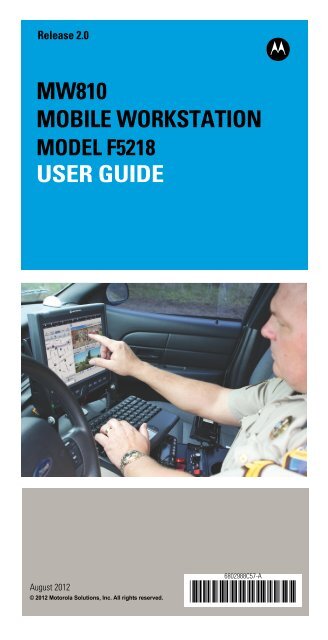
Release 2.0<br />
<strong>MW810</strong><br />
MOBILE WORKSTATION<br />
MODEL F5218<br />
USER GUIDE<br />
b<br />
August 2012<br />
© 2012 <strong>Motorola</strong> <strong>Solutions</strong>, Inc. All rights reserved.<br />
6802988C57-A<br />
@6802988C57@
Contents<br />
COMPUTER SOFTWARE COPYRIGHTS................... iii<br />
Document Copyrights................................................... iii<br />
Disclaimer..................................................................... iii<br />
Post-warranty Service .................................................. vi<br />
How to identify the workstation release number........... vii<br />
Using this Manual......................................................... viii<br />
Who Should Use this <strong>Guide</strong> ...................................... viii<br />
Related Documentation................................................ viii<br />
Notational Conventions ................................................ ix<br />
FCC Information ........................................................... ix<br />
FCC Grant of Equipment Authorization For <strong>MW810</strong><br />
Release 2.0 .................................................................. x<br />
<strong>Workstation</strong> Radio Combinations ................................. xi<br />
European Union Notification......................................... xi<br />
Conformity for RoHS Compliance ................................ xi<br />
Equipment Disposal ..................................................... xi<br />
Performance & Reliability of the Global Positioning System... xii<br />
Safety Instructions........................................................ xii<br />
What is the <strong>MW810</strong> <strong>Mobile</strong> <strong>Workstation</strong> .............. 1<br />
The CPU Box ............................................................... 2<br />
The Display .................................................................. 3<br />
Getting the <strong>MW810</strong> <strong>Mobile</strong> <strong>Workstation</strong> Running .. 4<br />
Unpacking .................................................................... 4<br />
Starting the Computer .................................................. 4<br />
Shutting Down the Computer ....................................... 5<br />
Turning Off................................................................ 5<br />
Taking a Look at the <strong>MW810</strong> <strong>Mobile</strong> <strong>Workstation</strong> .. 6<br />
CPU Box - Front Panel Components ........................... 6<br />
CPU Box - Backpanel Components ............................. 8<br />
CPU Box - Bottom Side View ....................................... 12<br />
Hard Disk Drive/Solid State Disk Compartment .......... 12<br />
12.1" Display Front-right Components ......................... 14<br />
12.1" Display - Backpanel Components ....................... 18<br />
8.4" Display Front-right Components ........................... 20<br />
8.4" Display - Backpanel Components ......................... 24<br />
Software Tools.............................................................. 25<br />
Working with Two Display Units ................................... 25<br />
The Keyboard ........................................................ 26<br />
Keyboard Illumination................................................... 27<br />
Illumination level ...................................................... 27<br />
© 2012 <strong>Motorola</strong> <strong>Solutions</strong>, Inc. 6802988C57-A<br />
August, 2012
Duration of the keyboard illumination ..................... 27<br />
Special Characters.................................................... 27<br />
Keypad mode............................................................. 27<br />
Touch Pad .................................................................... 28<br />
<strong>MW810</strong> <strong>Mobile</strong> <strong>Workstation</strong> Basic Operations....... 29<br />
Power On ..................................................................... 29<br />
Power Off ..................................................................... 29<br />
Sleep State ................................................................... 29<br />
Hibernation State.......................................................... 30<br />
Display Blackout Mode................................................. 30<br />
Night Mode ................................................................... 30<br />
Entering Sleep State Manually.................................. 31<br />
Wake Up from Sleep State......................................... 31<br />
Brightness Control........................................................ 31<br />
12.1” Display On-Screen-Display (OSD) Menu............ 32<br />
8.4” Display On-Screen-Display (OSD) Menu.............. 33<br />
Troubleshooting ..................................................... 34<br />
Maintenance .......................................................... 36<br />
Cleaning Materials........................................................ 36<br />
Cleaning Directions ...................................................... 36<br />
Getting Assistance From <strong>Motorola</strong>......................... 37<br />
ii
COMPUTER SOFTWARE COPYRIGHTS<br />
The <strong>Motorola</strong> products described in this instruction manual may<br />
include copyrighted <strong>Motorola</strong> <strong>Solutions</strong> computer programs stored in<br />
semiconductor memories or other media. Laws in the United States<br />
and other countries preserve for <strong>Motorola</strong> <strong>Solutions</strong> certain exclusive<br />
rights for copyrighted computer programs, including the exclusive<br />
right to copy or reproduce in any form the copyrighted computer<br />
program. Accordingly, any copyrighted <strong>Motorola</strong> <strong>Solutions</strong> computer<br />
programs contained In the <strong>Motorola</strong> <strong>Solutions</strong> products described in<br />
this instruction manual may not be copied or reproduced in any<br />
manner without the express written permission of <strong>Motorola</strong> <strong>Solutions</strong>.<br />
Furthermore, the purchase of <strong>Motorola</strong> <strong>Solutions</strong> products shall not<br />
be deemed to grant either directly or by implication, estoppel. or<br />
otherwise. any license under the copyrights, patents or patent<br />
applications of <strong>Motorola</strong> <strong>Solutions</strong>, except for the normal nonexclusive,<br />
royalty free license to use that arises by operation of law in<br />
the sale of a product.<br />
EPS – 34440- B<br />
Document Copyrights<br />
No duplication or distribution of this document or any portion thereof<br />
shall take place without the express written permission of <strong>Motorola</strong><br />
<strong>Solutions</strong>. No part of this manual may be reproduced, distributed, or<br />
transmitted in any form or by any means, electronic or mechanical,<br />
for any purpose without the express written permission of <strong>Motorola</strong><br />
<strong>Solutions</strong>.<br />
Disclaimer<br />
The information in this document is carefully examined, and is<br />
believed to be entirely reliable. However, no responsibility is<br />
assumed for inaccuracies.<br />
Furthermore, <strong>Motorola</strong> <strong>Solutions</strong> reserves the right to make changes<br />
to any products herein to improve readability, function, or design.<br />
<strong>Motorola</strong> <strong>Solutions</strong> does not assume any liability arising out of the<br />
applications or use of any product or circuit described herein; nor<br />
does it cover any license under its patent rights nor the rights of<br />
others.<br />
LIMITED WARRANTY<br />
MOTOROLA SOLUTIONS <strong>MW810</strong> MOBILE<br />
WORKSTATION<br />
This warranty applies within the fifty (50) United States, the District<br />
of Columbia and Canada, and is effective for <strong>MW810</strong> <strong>Mobile</strong><br />
<strong>Workstation</strong> shipments as of June 1, 2008.<br />
If any affected product is being purchased in response to a <strong>Motorola</strong><br />
<strong>Solutions</strong> proposal containing a different communication products<br />
warranty, the warranty contained in that proposal will apply to such<br />
affected product. Otherwise, the following warranty applies.<br />
iii
I. WHAT THIS WARRANTY COVERS AND FOR HOW LONG:<br />
<strong>Motorola</strong> <strong>Solutions</strong> Inc. or, if applicable, <strong>Motorola</strong> <strong>Solutions</strong> Canada<br />
Limited ("<strong>Motorola</strong> <strong>Solutions</strong>") warrants the <strong>Motorola</strong> <strong>Solutions</strong><br />
<strong>MW810</strong> <strong>Mobile</strong> <strong>Workstation</strong> (“Product”) against material defects in<br />
material and workmanship under normal use and service for a period<br />
of Three (3) Years from the date of shipment.<br />
<strong>Motorola</strong> <strong>Solutions</strong>, at its option, will at no charge either repair the<br />
Product (with new or reconditioned parts), replace it with the same or<br />
equivalent Product (using new or reconditioned Product), or refund<br />
the purchase price of the Product during the warranty period provided<br />
purchaser notifies <strong>Motorola</strong> <strong>Solutions</strong> according to the terms of<br />
this warranty. Repaired or replaced Product is warranted for the balance<br />
of the original applicable warranty period. All replaced parts of<br />
the Product shall become the property of <strong>Motorola</strong> <strong>Solutions</strong>.<br />
This express limited warranty is extended by <strong>Motorola</strong> <strong>Solutions</strong> to<br />
the original end user purchaser purchasing the Product for purposes<br />
of leasing or for commercial, industrial, or governmental use only,<br />
and is not assignable or transferable to any other party. This is the<br />
complete warranty for the Product manufactured by <strong>Motorola</strong> <strong>Solutions</strong>.<br />
<strong>Motorola</strong> <strong>Solutions</strong> assumes no obligations or liability for additions<br />
or modifications to this warranty unless made in writing and<br />
signed by an officer of <strong>Motorola</strong> <strong>Solutions</strong>. Unless made in a separate<br />
written agreement between <strong>Motorola</strong> <strong>Solutions</strong> and the original<br />
end user purchaser, <strong>Motorola</strong> <strong>Solutions</strong> does not warrant the installation,<br />
maintenance or service of the Product.<br />
<strong>Motorola</strong> <strong>Solutions</strong> cannot be responsible in any way for any ancillary<br />
equipment not furnished by <strong>Motorola</strong> <strong>Solutions</strong>, which is attached to<br />
or used in connection with the Product, or for operation of the Product<br />
with any ancillary equipment, and all such equipment is expressly<br />
excluded from this warranty. Because each system that may use the<br />
Product is unique, <strong>Motorola</strong> <strong>Solutions</strong> disclaims liability for range,<br />
coverage, or operation of the system as a whole under this warranty.<br />
II. GENERAL PROVISIONS:<br />
This warranty sets forth the full extent of <strong>Motorola</strong> <strong>Solutions</strong> responsibilities<br />
regarding the Product. Repair, replacement or refund of the<br />
purchase price, at <strong>Motorola</strong> <strong>Solutions</strong> option, is the exclusive remedy.<br />
THIS WARRANTY IS GIVEN IN LIEU OF ALL OTHER<br />
EXPRESS WARRANTIES. MOTOROLA SOLUTIONS DISCLAIMS<br />
ALL OTHER WARRANTIES OR CONDITIONS, EXPRESS OR<br />
IMPLIED, INCLUDING THE IMPLIED WARRANTIES OR CONDI-<br />
TIONS OF MERCHANTABILITY AND FITNESS FOR A PARTICU-<br />
LAR PURPOSE. IN NO EVENT SHALL MOTOROLA SOLUTIONS<br />
BE LIABLE FOR DAMAGES IN EXCESS OF THE PURCHASE<br />
PRICE OF THE PRODUCT, FOR ANY LOSS OF USE, LOSS OF<br />
TIME, INCONVENIENCE, COMMERCIAL LOSS, LOST PROFITS<br />
OR SAVINGS OR OTHER INCIDENTAL, SPECIAL, INDIRECT OR<br />
CONSEQUENTIAL DAMAGES ARISING OUT OF THE USE OR<br />
INABILITY TO USE SUCH PRODUCT, TO THE FULL EXTENT<br />
SUCH MAY BE DISCLAIMED BY LAW.<br />
III. HOW TO GET WARRANTY SERVICE:<br />
Purchaser must notify <strong>Motorola</strong> <strong>Solutions</strong> representative or call<br />
<strong>Motorola</strong> <strong>Solutions</strong> Customer Response Center at 1-800-247-2346<br />
within the applicable warranty period for information regarding warranty<br />
service.<br />
iv
IV. WHAT THIS WARRANTY DOES NOT COVER:<br />
A) Defects or damage resulting from use of the Product in other<br />
than its normal and customary manner.<br />
B) Defects or damage from misuse, accident, water, or neglect.<br />
C) Defects or damage from improper testing, operation, maintenance,<br />
installation, alteration, modification, or adjustment.<br />
D) Breakage or damage to antennas unless caused directly by<br />
defects in material workmanship.<br />
E) A Product subjected to unauthorized Product modifications, disassemblies<br />
or repairs (including, without limitation, the addition<br />
to the Product of non-<strong>Motorola</strong> <strong>Solutions</strong> supplied equipment)<br />
which adversely affect performance of the Product or interfere<br />
with <strong>Motorola</strong> <strong>Solutions</strong> normal warranty inspection and testing<br />
of the Product to verify any warranty claim.<br />
F) Product that has had the serial number removed or made illegible.<br />
G) Batteries (they carry their own separate limited warranty).<br />
H) Freight costs to the repair depot.<br />
I) A Product which, due to illegal or unauthorized alteration of the<br />
software/firmware in the Product, does not function in accordance<br />
with <strong>Motorola</strong> <strong>Solutions</strong> published specifications or with<br />
the FCC type acceptance labeling in effect for the Product at the<br />
time the Product was initially distributed from <strong>Motorola</strong> <strong>Solutions</strong>.<br />
J) Scratches or other cosmetic damage to Product surfaces that<br />
does not affect the operation of the Product.<br />
K) That the software in the Product will meet the purchaser's<br />
requirements or that the operation of the software will be uninterrupted<br />
or error-free.<br />
L) Normal and customary wear and tear.<br />
M) Non-<strong>Motorola</strong> <strong>Solutions</strong> manufactured equipment unless bearing<br />
a <strong>Motorola</strong> <strong>Solutions</strong> Part Number in the form of an alphanumeric<br />
number (i.e., TDE6030B).<br />
N) Lift trucks if required for installation, removal, replacement or<br />
repair of the <strong>Motorola</strong> <strong>Solutions</strong>-supplied products.<br />
O) Dispatch to remote site locations.<br />
P) Loading of software upgrades or fixes into the devices.<br />
V. GOVERNING LAW:<br />
In the case of a Product sold in the United States and Canada, this<br />
Warranty is governed by the laws of the State of Illinois and the Province<br />
of Ontario, respectively.<br />
VI. PATENT AND SOFTWARE PROVISIONS:<br />
<strong>Motorola</strong> <strong>Solutions</strong> will defend, at its own expense, any suit brought<br />
against the end user purchaser to the extent that it is based on a<br />
claim that the Product or its parts infringe a United States patent, and<br />
<strong>Motorola</strong> <strong>Solutions</strong> will pay those costs and damages finally awarded<br />
against the end user purchaser in any such suit which are attributable<br />
to any such claim, but such defense and payments are conditioned<br />
on the following:<br />
A) that <strong>Motorola</strong> <strong>Solutions</strong> will be notified promptly in writing by such<br />
purchaser of any notice of such claim;<br />
B) that <strong>Motorola</strong> <strong>Solutions</strong> will have sole control of the defense of<br />
such suit and all negotiations for its settlement or compromise;<br />
and<br />
C) should the Product or its parts become, or in <strong>Motorola</strong> <strong>Solutions</strong><br />
opinion be likely to become, the subject of a claim of infringement<br />
of a United States patent, that such purchaser will permit<br />
v
<strong>Motorola</strong> <strong>Solutions</strong>, at its option and expense, either to procure<br />
for such purchaser the right to continue using the Product or its<br />
parts or to replace or modify the same so that it becomes noninfringing<br />
or to grant such purchaser a credit for the Product or<br />
its parts as depreciated and accept its return. The depreciation<br />
will be an equal amount per year over the lifetime of the Product<br />
or its parts as established by <strong>Motorola</strong> <strong>Solutions</strong>.<br />
VII. FOR AUSTRALIA ONLY:<br />
This warranty is given by <strong>Motorola</strong> <strong>Solutions</strong> Australia Pty Limited<br />
(ABN 16 004 742 312) of Tally Ho Business Park, 10 Wesley Court.<br />
Burwood East, Victoria.<br />
Our goods come with guarantees that cannot be excluded under the<br />
Australia Consumer Law. You are entitled to a replacement or refund<br />
for a major failure and compensation for any other reasonably foreseeable<br />
loss or damage. You are also entitled to have the goods<br />
repaired or replaced if the goods fail to be of acceptable quality and<br />
the failure does not amount to a major failure.<br />
<strong>Motorola</strong> <strong>Solutions</strong> Australia's limited warranty above is in addition to<br />
any rights and remedies you may have under the Australian Consumer<br />
Law.<br />
If you have any queries, please call <strong>Motorola</strong> <strong>Solutions</strong> Australia at<br />
1800 457 439. You may also visit our website: http://www.motorola.com/Business/XA-EN/Pages/Contact_Us<br />
for the most updated<br />
warranty terms.<br />
<strong>Motorola</strong> <strong>Solutions</strong> will have no liability with respect to any claim of<br />
patent infringement which is based upon the combination of the<br />
Product or its parts furnished hereunder with software, apparatus or<br />
devices not furnished by <strong>Motorola</strong> <strong>Solutions</strong>, nor will <strong>Motorola</strong> <strong>Solutions</strong><br />
have any liability for the use of ancillary equipment or software<br />
not furnished by <strong>Motorola</strong> <strong>Solutions</strong> which is attached to or used in<br />
connection with the Product. The foregoing states the entire liability<br />
of <strong>Motorola</strong> <strong>Solutions</strong> with respect to infringement of patents by the<br />
Product or any its parts thereof.<br />
Laws in the United States and other countries preserve for <strong>Motorola</strong><br />
<strong>Solutions</strong> certain exclusive rights for copyrighted <strong>Motorola</strong> <strong>Solutions</strong><br />
software such as the exclusive rights to reproduce in copies and<br />
distribute copies of such <strong>Motorola</strong> <strong>Solutions</strong> software. <strong>Motorola</strong><br />
<strong>Solutions</strong> software may be used in only the Product in which the<br />
software was originally embodied and such software in such Product<br />
may not be replaced, copied, distributed, modified in any way, or<br />
used to produce any derivative thereof. No other use including,<br />
without limitation, alteration, modification, reproduction, distribution,<br />
or reverse engineering of such <strong>Motorola</strong> <strong>Solutions</strong> software or<br />
exercise of rights in such <strong>Motorola</strong> <strong>Solutions</strong> software is permitted.<br />
No license is granted by implication, estoppel or otherwise under<br />
<strong>Motorola</strong> <strong>Solutions</strong> patent rights or copyrights.<br />
Post-warranty Service<br />
Repair Service Advantage (RSA) programs are available at<br />
additional cost, with options of 1-year RSA (covering year 4) and 2-<br />
year RSA (covering years 4 and 5).<br />
All other warranty terms and conditions remain the same.<br />
vi
How to identify the workstation release<br />
number<br />
This manual relates to <strong>MW810</strong> <strong>Mobile</strong> <strong>Workstation</strong> Release<br />
2.0. The Release Number reflects the type of hardware and<br />
software installed inside the <strong>MW810</strong> <strong>Mobile</strong> <strong>Workstation</strong>.<br />
When receiving the <strong>MW810</strong> <strong>Mobile</strong> <strong>Workstation</strong>, the<br />
Release Number is included with the documentation<br />
attached to the shipping package.<br />
To identify Release 2.0 on <strong>MW810</strong> <strong>Mobile</strong> <strong>Workstation</strong> units,<br />
refer to Figure1.<br />
Release Number<br />
<strong>MW810</strong> R2.0<br />
Release Number<br />
Figure 1. Release Number on <strong>MW810</strong> <strong>Mobile</strong> <strong>Workstation</strong> Units.<br />
To identify Release 2.0 after installing the workstation, perform<br />
the following:<br />
Click Start In and in the search box enter msinfo32. The CPU<br />
type will appear in the processor description.<br />
The CPU type will appear in the processor description:<br />
• Intel® Core TM i7-3610QE 2.3 GHz Quad core processor<br />
• Intel® Core TM i5-3610ME 2.7 GHz Dual core processor<br />
• Intel® Core TM B810 1.6 GHz Celeron processor<br />
vii
Using this Manual<br />
Before using this manual and the products it describe, be<br />
sure to read the Safety instructions, Warranty information<br />
and the FCC information that follows.<br />
Who Should Use this <strong>Guide</strong><br />
This guide is intended for staff that operates the <strong>MW810</strong><br />
<strong>Mobile</strong> <strong>Workstation</strong> in vehicles. This guide assumes that<br />
reader is familiar with basic Microsoft® Windows® 7 Professional<br />
operations. When this is not the case, be sure to<br />
read the documentation applicable to your version of Windows.<br />
Related Documentation<br />
This guide describes the <strong>MW810</strong> <strong>Mobile</strong> <strong>Workstation</strong> and<br />
provides basic knowledge about the device.<br />
Please note that although this guide refers to hardware and<br />
software components supplied with the <strong>MW810</strong> <strong>Mobile</strong><br />
<strong>Workstation</strong>, it does not provide full component descriptions.<br />
For additional information refer to the following publications:<br />
Publication Number<br />
6802983C01<br />
6802988C56<br />
6802988C40<br />
6802988C41<br />
6802988C42<br />
Description<br />
<strong>Motorola</strong> <strong>MW810</strong> <strong>Mobile</strong> <strong>Workstation</strong>,<br />
Product Safety and RF Exposure for<br />
mobile workstation with two-way<br />
radios installed in vehicles leaflet<br />
(multilingual)<br />
<strong>Motorola</strong> <strong>MW810</strong> <strong>Mobile</strong> <strong>Workstation</strong>,<br />
R2.0, Vehicle Installation Manual<br />
<strong>Motorola</strong> <strong>MW810</strong> <strong>Mobile</strong> <strong>Workstation</strong>,<br />
R2.0, Quick Reference <strong>Guide</strong><br />
(multilingual)<br />
<strong>Motorola</strong> <strong>MW810</strong> <strong>Mobile</strong> <strong>Workstation</strong>,<br />
R2.0, Software Development Kit<br />
<strong>Motorola</strong> <strong>MW810</strong> <strong>Mobile</strong> <strong>Workstation</strong>,<br />
R2.0, Administrator <strong>Guide</strong><br />
viii
For the latest version of this guide and other <strong>MW810</strong> <strong>Mobile</strong><br />
<strong>Workstation</strong> manuals logon to: www.motorola.com/enterprisemobility/manuals<br />
or www.motorola.com/<strong>MW810</strong><br />
This guide is designed to supplement the online or contextsensitive<br />
help provided with each software application.<br />
Please review this information to ensure proper use of the<br />
product. For software and operation system issues, refer to<br />
Microsoft® Windows® 7 Professional documentation.<br />
Notational Conventions<br />
Throughout this publication, you will notice the use of cautions<br />
and notes. These notations are used to emphasize that<br />
safety hazards exist, and care must be taken.<br />
CAUTION<br />
Indicates a potentially hazardous situation which, if not<br />
avoided, may result in minor or moderate injury.<br />
! CAUTION may also be used to alert against unsafe<br />
Caution practices and property-damage-only accident hazards.<br />
Do not proceed beyond a CAUTION until the indicated conditions<br />
are fully understood and met.<br />
FCC Information<br />
FCC Interference<br />
This device complies with Part 15 of the FCC Rules. Operation<br />
is subject to the following two conditions:<br />
(1) This device may not cause harmful interference.<br />
(2) This device must accept any interference received, including<br />
interference that may cause undesired operation.<br />
For detailed product safety and RF exposure, refer to Safety<br />
and General Information leaflet, <strong>Motorola</strong> publication number<br />
6802983C01.<br />
Changes or modifications made in the CPU Box or<br />
Display, not expressly approved by <strong>Motorola</strong>, will void<br />
the user's authority to operate the equipment.<br />
!<br />
Caution<br />
ix
FCC Grant of Equipment Authorization For<br />
<strong>MW810</strong> Release 2.0<br />
<strong>MW810</strong> <strong>Mobile</strong><br />
<strong>Workstation</strong><br />
Option No<br />
Radio Type<br />
Frequency Range MHz<br />
FCC Grant<br />
ID<br />
Power<br />
Output<br />
Watt<br />
VA00806AA<br />
(802.11a/b/g/n)<br />
WLAN<br />
2412.0- 2462.0<br />
5180.0 - 5240.0<br />
5260.0 - 5320.0<br />
5500.0 - 5700.0<br />
5745.0 - 5825.0<br />
PD9633ANH<br />
0.048<br />
0.049<br />
0.049<br />
0.05<br />
0.05<br />
VA00804AA<br />
(Verizon)<br />
MC7750<br />
LTE B13: 779.5 - 784.5<br />
BC0: 824.7 - 848.31<br />
BC1: 1850.25 - 1908.75<br />
N7NMC7750<br />
0.227<br />
0.34<br />
0.337<br />
VA00801AA<br />
MC8795V<br />
WCDMA B1: 1920 - 1980<br />
WCDMA B2: 1850 - 1910<br />
WCDMA B5: 824 - 849<br />
WCDMA B6: 830 - 840<br />
WCDMA B8: 880 - 915<br />
GSM 850: 824 - 849<br />
EGSM 900: 880 - 915<br />
DCS 1800: 1710 - 1785<br />
PCS 1900: 1850 - 1910<br />
N7NMC8795<br />
0.251<br />
0.251<br />
0.251<br />
0.251<br />
0.251<br />
2<br />
2<br />
1<br />
1<br />
VA00017AB<br />
Bluetooth<br />
Radio<br />
Module -<br />
Spread<br />
Spectrum<br />
Transmitter<br />
2402.0 - 2480.0<br />
QDS-<br />
BRCM1043<br />
0.00267<br />
x
<strong>Workstation</strong> Radio Combinations<br />
The <strong>MW810</strong> <strong>Mobile</strong> <strong>Workstation</strong> can be configured for simultaneous<br />
transmission by the following radio combinations:<br />
<strong>MW810</strong> <strong>Mobile</strong> <strong>Workstation</strong> Option Number.<br />
Radio Type<br />
VA00804AA<br />
VA00806AA<br />
WWAN-MC7750 Verizon<br />
WLAN - Intel Centrino<br />
Ultimate - N 6300<br />
<strong>MW810</strong> <strong>Mobile</strong> <strong>Workstation</strong> Option Number.<br />
VA00801AA<br />
VA00806AA<br />
Radio Type<br />
WWAN-MC8795V<br />
WLAN - Intel Centrino<br />
Ultimate - N 6300<br />
European Union Notification<br />
This <strong>Motorola</strong> product can be sold, or put into service for the<br />
first time, anywhere in the European community.<br />
The CE mark is the official marking required by the<br />
European Community for all Electric and Electronic equipment<br />
that will be sold, or put into service for the first time, anywhere<br />
in the European community.<br />
Conformity for RoHS Compliance<br />
This <strong>Motorola</strong> product is in compliance with the essential<br />
requirements and other relevant provisions of Directive 2002/<br />
95/EC, Restriction of the use of certain Hazardous Substances<br />
(RoHS) in electrical and electronic equipment.<br />
Equipment Disposal<br />
Please do not dispose of Electronic and Electric<br />
Equipment or Electronic and Electric Accessories with your<br />
household waste. In some countries or regions, collection<br />
systems have been set up to handle waste of electrical and<br />
electronic equipment. In European Union countries, please<br />
contact your local equipment supplier representative or service<br />
center for information about the waste collection system<br />
in your country.<br />
xi
Performance & Reliability of the Global<br />
Positioning System<br />
Underwriters Laboratories Inc. (UL) has not tested the performance<br />
or reliability of the Global Positioning System (GPS)<br />
hardware, operating software or other aspects of this product.<br />
UL has only tested for fire, shock or casualties as outlined<br />
in UL's Standard(s) for Safety for Information<br />
Technology Equipment, UL60950-1. UL Certification does not<br />
cover the performance or reliability of the GPS hardware and<br />
GPS operating software. UL MAKES NO REPRESENTATIONS,<br />
WARRANTIES OR CERTIFICATIONS WHATSOEVER REGARD-<br />
ING THE PERFORMANCE OR RELIABILITY OF ANY GPS<br />
RELATED FUNCTIONS OF THIS PRODUCT.<br />
Trademarks<br />
• Microsoft®, Windows® 7 and the Windows logo are<br />
registered trademarks of Microsoft Corporation.<br />
• Intel®, Intel® Core TM and Centrino® are registered<br />
trademarks of Intel Corporation.<br />
• The Bluetooth TM trademarks are owned by their proprietor<br />
and used by <strong>Motorola</strong> <strong>Solutions</strong>, Inc. under license in the<br />
U.S. and other countries.<br />
• Trimble® is a registered trademark of Trimble Navigation<br />
Limited.<br />
• U-Blox® is a registered trademark of U-Blox AG.<br />
• MOTOROLA SOLUTIONS and the stylized M Logo are<br />
registered in the U.S. Patent and Trademark Office. All<br />
other product or service names are the property of their<br />
respective owners. © <strong>Motorola</strong> <strong>Solutions</strong>, Inc. 2012.<br />
Safety Instructions<br />
• Use of the product during driving should be coordinated<br />
with the government-mandated driving rules for specific<br />
users (such as policemen, firemen, etc.).<br />
• Do not connect or disconnect cables while your <strong>MW810</strong><br />
<strong>Mobile</strong> <strong>Workstation</strong> is turned on.<br />
xii<br />
!<br />
Caution<br />
Reduce the risk of fire or electric shock by<br />
following basic safety instructions:
• Protect your <strong>MW810</strong> <strong>Mobile</strong> <strong>Workstation</strong> from liquids.<br />
Keep your <strong>MW810</strong> <strong>Mobile</strong> <strong>Workstation</strong> away from<br />
water.<br />
• Be sure that all power cord connections are securely<br />
plugged into receptacles.<br />
Avoid damage to the <strong>MW810</strong> <strong>Mobile</strong> <strong>Workstation</strong> by following<br />
basic safety instructions:<br />
• Your <strong>MW810</strong> <strong>Mobile</strong> <strong>Workstation</strong> generates heat when<br />
turned on. Ensure that the CPU Box is always mounted in<br />
the CPU Box mounting trunnion provided with each system,<br />
to ensure proper airflow for CPU Box fans.<br />
• The <strong>MW810</strong> <strong>Mobile</strong> <strong>Workstation</strong> is very sensitive to<br />
uncontrolled shut down. Never turn off the <strong>MW810</strong><br />
<strong>Mobile</strong> <strong>Workstation</strong> by turning off the power supply or<br />
by disconnection of the power cable.<br />
• Hard disk drive performance and lifetime could be shortened<br />
if your <strong>MW810</strong> <strong>Mobile</strong> <strong>Workstation</strong> is not used for<br />
long periods. Do not leave the <strong>MW810</strong> <strong>Mobile</strong> <strong>Workstation</strong><br />
unused for more than 3 months.<br />
• Your <strong>MW810</strong> <strong>Mobile</strong> <strong>Workstation</strong> automatically shuts<br />
down when the internal temperature exceeds the upper<br />
limit of the valid range.<br />
• Forcing SIM or Express cards into computer slots at an<br />
angle may damage slot connectors.<br />
• If the <strong>MW810</strong> <strong>Mobile</strong> <strong>Workstation</strong> stops responding, you<br />
can turn it off by holding the Power button of the CPU<br />
Box or Display pressed for more than 6 seconds. Be<br />
aware that this method of shutdown may damage your<br />
Hard Disk Drive.<br />
• Do not insert or remove cards when the <strong>MW810</strong> <strong>Mobile</strong><br />
<strong>Workstation</strong> is in Sleep state. Before you insert or<br />
remove a card, make sure that you exit all software<br />
applications that access the card.<br />
xiii
What is the <strong>MW810</strong> <strong>Mobile</strong> <strong>Workstation</strong><br />
The <strong>MW810</strong> <strong>Mobile</strong> <strong>Workstation</strong> series is one of<br />
<strong>Motorola</strong> <strong>Solutions</strong> highest-performing and most rugged data<br />
communication and computing solutions. It is specifically<br />
designed for the harsh conditions of the mobile environment,<br />
which is not suitable for conventional notebook or desktop<br />
computers.<br />
The <strong>MW810</strong> <strong>Mobile</strong> <strong>Workstation</strong> is a versatile three-piece<br />
design with separate display (12.1” or 8.4”), Central Processing<br />
Unit (CPU) Box and a keyboard. A choice of configurations<br />
enables fitting the workstation to a variety of vehicle types<br />
and customizing installations to meet specific owner needs<br />
and specifications.<br />
The <strong>MW810</strong> <strong>Mobile</strong> <strong>Workstation</strong> is a multipurpose mobile<br />
computer with capability to provide seamless mobility. The<br />
workstation supports multiple internal radios, providing reliable<br />
connectivity across a number of dissimilar public and<br />
private data networks. Among its many communication interfaces,<br />
the workstation incorporates video (option) and audio<br />
inputs, as well as an internal GPS or Dead Reckoning GPS<br />
module options, ensuring reliable and accurate vehicle location<br />
notification.<br />
An optional Automatic License Plate Recognition (ALPR) system<br />
enables to capture license plate images from up to four<br />
imaging sources installed in a vehicle. The plate numbers are<br />
compared against database or hot list.<br />
The workstation is powered by a family of high-tier processors<br />
with extensive memory.<br />
In addition to the basic multiple port connections option (the<br />
“No I/O Expansion Board, R2.X” option), the <strong>MW810</strong> <strong>Mobile</strong><br />
<strong>Workstation</strong> is available with three optional expansion<br />
boards:<br />
1. The “Comm & Video I/O Expansion Board, R2.X”<br />
2. The “ALPR I/O Expansion Board, R2.X”<br />
3. The “Serial & USB I/O Expansion Board, R2.X”<br />
1
The CPU Box<br />
The CPU Box is a high-performance computing platform for<br />
mission-critical applications with numerous computing, data<br />
storage and communication capabilities. It is designed to be<br />
permanently mounted and serve as a hub to the computing<br />
and communications network in the vehicle.<br />
Key features of the CPU Box:<br />
• Windows 7 Professional 32b or 64b Operating System<br />
(OS).<br />
• Intel® Core TM i7-3610QE 2.3 GHz quad 6 MB cash processor<br />
or Intel® Core TM i5-3610ME 2.7 GHz Dual Core 3<br />
MB cash processor or Intel® Core TM B810 1.6 GHz Dual<br />
Core 2 MB cash processor.<br />
• Extendable system memory – 2 slots for DDR3 SODIMM<br />
modules, 4GB each.<br />
• Removable 500GB Hard Disk Drive or 256GB removable<br />
Solid State Disk (optional).<br />
• 64GB mSATA card (optional).<br />
• External Serial Advanced Technology Attachment +<br />
power (eSATAp) port for fast data transfer to/from an<br />
external storage device. eSATA is only available with the<br />
“Serial & USB I/O Expansion Board, R2.X”.<br />
• A wide range of internal/external interfaces available,<br />
such as: USB 3.0 and 2.0 ports, Ethernet 1GB ports, RS-<br />
232 ports, audio and analog video input.<br />
• Optional Wireless LAN (WLAN) connection using Intel®<br />
Wireless WiFi adapter IEEE 802.11a/b/g/n.<br />
• Optional Wireless Wide-Area Network (WWAN) modules<br />
offering wireless data solutions over 3G and 4G LTE<br />
networks, subject to governmental and carrier certifications<br />
as well as network availability in your area.<br />
• Built-in High Speed Packet Access (HSPA) receivers.<br />
• Optional built-in GPS receivers, including choices of protocols<br />
supported and optional dead reckoning intelligence<br />
when satellite data is missing.<br />
• Compliance with Trusted Platform Module (TPM) 1.2<br />
specification requirements (module contained inside the<br />
CPU Box).<br />
2
• Vehicle ignition sense for using the vehicle key to turn<br />
the workstation On/Off.<br />
• Programmable general purpose inputs/outputs.<br />
• Simultaneous use by two independent users, each using<br />
a separate display and keyboard.<br />
• Custom-designed cables/adaptors for connection to DVI/<br />
RGB 3rd party Display.<br />
• Fully-Rugged mechanical design.<br />
• Smart Card reader (optional).<br />
• Express Card slot.<br />
The Display<br />
The <strong>MW810</strong> <strong>Mobile</strong> <strong>Workstation</strong> offers three optional rugged<br />
displays:<br />
• 12.1” XGA high brightness display: TFT-technology display<br />
with 1500 NIT (1500 cd/m2) LED backlighting to<br />
ensure viewing under bright light conditions.<br />
• 12.1” XGA standard brightness display: TFT-technology<br />
display with 500 NIT (500 cd/m2) LED backlighting.<br />
• 8.4” SVGA high brightness display: TFT-technology display<br />
with 800 NIT (800 cd/m2) LED backlighting.<br />
The displays offer the following features:<br />
• Screen made of tempered glass, with a protective film to<br />
prevent glass shattering in the event of breakage.<br />
• Resistive Touchscreen can be activated even with a<br />
gloved finger or a stylus pen.<br />
• Integrated Smart Card Reader compartment (optional,<br />
only on 12.1“ displays). Integrated Smart Card reader<br />
slot allows a smart card to be completely IP-54 sealed.<br />
Note that the Smart Card reader option does not include<br />
a user application.<br />
• Sealing against moisture.<br />
• Optional built-in Bluetooth radio (only 12.1“Display) to<br />
provide wireless connection to personal area peripherals<br />
such as headset, mouse, printer etc.<br />
• Three USB 2.0 ports on 12.1“ displays and two on<br />
8.4“Display for connectivity to external USB devices.<br />
3
Getting the <strong>MW810</strong> <strong>Mobile</strong> <strong>Workstation</strong> Running<br />
This section guides you through procedures to get the<br />
<strong>MW810</strong> <strong>Mobile</strong> <strong>Workstation</strong> ready for operation.<br />
Unpacking<br />
Unpack your shipment and check the contents to ensure that<br />
you have received all the specified items. Save the packing<br />
carton and anti-static plastic bag for future storage and shipping.<br />
Both the shipping carton and the anti-static bags protect<br />
the <strong>MW810</strong> <strong>Mobile</strong> <strong>Workstation</strong> components from<br />
physical and electrostatic damage.<br />
After unpacking the shipping carton, the following items<br />
should be found if ordered as part of the system:<br />
• CPU Box<br />
• Display<br />
• Keyboard<br />
• Power Cords<br />
• CPU-to-Display(s) cable(s)<br />
• This <strong>User</strong> <strong>Guide</strong> - 6802988C57<br />
• <strong>Motorola</strong> <strong>MW810</strong> <strong>Mobile</strong> <strong>Workstation</strong> Quick Reference<br />
<strong>Guide</strong> (multilingual) - 6802988C40<br />
• RF Safety and General Information booklet - 6802983C01<br />
• Accessory cables and/or antenna(s) (may ship in one or<br />
more separate boxes from main system)<br />
• DVD with Windows 7 Professional OS<br />
• Recovery DVD<br />
Inspect all the items. If any item is missing or damaged,<br />
notify your <strong>Motorola</strong> <strong>Solutions</strong> Customer Service representative<br />
immediately.<br />
Starting the Computer<br />
Your computer OS is already installed on the Hard Disk Drive<br />
(HDD) or solid State Disk Drive (SDD) or mSATA memory unit<br />
(optional).<br />
After ensuring proper installation of the <strong>MW810</strong> <strong>Mobile</strong><br />
<strong>Workstation</strong>, perform the following steps to turn on the<br />
<strong>MW810</strong> <strong>Mobile</strong> <strong>Workstation</strong>:<br />
4
1. Press the power button on the front panel of the CPU Box<br />
or Display- both buttons perform identical function.<br />
2. Wait for the boot process to start and for Windows desktop<br />
to appear.<br />
NOTE: The <strong>MW810</strong> <strong>Mobile</strong> <strong>Workstation</strong> can be configured to<br />
start by pressing the:<br />
• Vehicle ignition switch<br />
• CPU power button<br />
• Display power button<br />
The workstation can also start using a combined operations<br />
of the items described above with selectable time-delay. For<br />
more information, refer to <strong>Motorola</strong> <strong>Solutions</strong> <strong>MW810</strong><br />
<strong>Mobile</strong> <strong>Workstation</strong>, R2.0, Administrator <strong>Guide</strong> P/N<br />
6802988C42.<br />
Shutting Down the Computer<br />
When you finish a working session, you can stop the computer<br />
by turning off the power or leaving the computer in<br />
Sleep or Hibernation mode.<br />
Turning Off<br />
Use the Windows OS Shut Down dialog box to turn off the<br />
<strong>MW810</strong> <strong>Mobile</strong> <strong>Workstation</strong>.<br />
NOTE: The <strong>MW810</strong> <strong>Mobile</strong> <strong>Workstation</strong> can be configured so<br />
that the vehicle ignition switch, the power button located on<br />
the CPU front panel, or the Display power button can turn it<br />
off.<br />
!<br />
Caution<br />
Remember to save important information before<br />
turning off your workstation.<br />
Be aware, that rapid turning off and on can damage<br />
your Hard Disk Drive. If you need to turn the <strong>MW810</strong><br />
<strong>Mobile</strong> <strong>Workstation</strong> on immediately after turning it<br />
off, always wait for the shut down process to<br />
complete.<br />
For more on turning Off, see “Power Off” on page 29.<br />
5
Taking a Look at the <strong>MW810</strong> <strong>Mobile</strong> <strong>Workstation</strong><br />
CPU Box - Front Panel Components<br />
Figure 2 shows the front panel components of the CPU Box.<br />
2<br />
Power LED<br />
1<br />
Power Button<br />
3<br />
4<br />
Express Card & SIMs Compartment<br />
Removable Hard Disk Drive/Solid State Disk Unit<br />
Figure 2. CPU Box - Front Panel Components<br />
1 Power Button<br />
The Power Button turns the <strong>MW810</strong> <strong>Mobile</strong> <strong>Workstation</strong><br />
power on and off (CPU Box & display). The button may also be<br />
configured for entering Sleep or Hibernation modes. Note<br />
that the <strong>MW810</strong> <strong>Mobile</strong> <strong>Workstation</strong> may also be configured<br />
to be turned on/off depending on the state of the vehicle ignition<br />
switch. Before powering on the CPU, ensure that the On/<br />
Off power switch on the backpanel of the CPU Box is in ON<br />
position (see Figure 3).<br />
2 Power LED<br />
The Power LED indicates the following status:<br />
• Green - Power on.<br />
• Amber - Sleep state. In Sleep state, the workstation<br />
switches to low-power consumption. When starting to<br />
use the <strong>MW810</strong>, it restores exactly to the last used<br />
screen position.<br />
6
NOTE: Amber my also show when Active Management<br />
Technology (AMT) mode is initiated when the <strong>MW810</strong> is<br />
powered off. In AMT mode, the <strong>MW810</strong> is remotely managed<br />
by IT grope of the agency.<br />
3 Removable Hard Disk Drive/Solid State Disk Unit<br />
The Hard Disk Drive (HDD)/Solid State Disk (SSD) is installed<br />
inside a removable unit. The unit is secured to the CPU Box by<br />
two screws.<br />
When a mSATA is used as a mass memory storage device<br />
instead of HDD or SSD, a cover panel is placed to seal the<br />
CPU Box. In such case, do not open this compartment.<br />
For more information refer to“Hard Disk Drive/Solid State<br />
Disk Compartment” on page 12.<br />
4 Express Card & SIMs Compartment<br />
The compartment contains Express card slot (size 34 or<br />
54mm) for memory devices and SIM cards that are required<br />
to activate the internal W-WAN radios. The compartment is<br />
completely sealed when the cover is closed and locked. Do<br />
not open this compartment unless service is required.<br />
7
CPU Box - Backpanel Components<br />
Figure 3 show the backpanel options of the CPU Box (for connection<br />
details, refer to <strong>MW810</strong> <strong>Mobile</strong> <strong>Workstation</strong>, Vehicle<br />
Installation Manual P/N 6802988C56).<br />
6<br />
5<br />
4<br />
3<br />
USB2<br />
2<br />
USB3<br />
1<br />
VIDEO<br />
DISPLAY 2<br />
COM 4<br />
LAN<br />
LAN<br />
USB<br />
ON<br />
7<br />
DISPLAY 1<br />
MAIN AUX<br />
W-WAN2<br />
IN<br />
LAN<br />
OUT<br />
COM 1<br />
W-LAN<br />
2 3 1<br />
AUX<br />
W-WAN1<br />
MAIN<br />
USB<br />
AUX GPS<br />
OFF<br />
PWR<br />
16<br />
17<br />
8 9 10 11 12 14 13 15<br />
Comm & Video I/O Expansion Board, R2.X<br />
DISPLAY 2<br />
LAN<br />
LAN<br />
ALPR<br />
USB<br />
ON<br />
OFF<br />
MAIN<br />
W-WAN2<br />
DISPLAY 1<br />
AUX<br />
IN<br />
LAN<br />
OUT<br />
COM 1<br />
W-LAN<br />
2 3 1<br />
AUX<br />
W-WAN1<br />
MAIN<br />
ALPR I/O Expansion Board, R2.X<br />
AUX<br />
USB<br />
GPS<br />
PWR<br />
ON<br />
OFF<br />
DISPLAY 1<br />
MAIN AUX<br />
LAN<br />
COM 1<br />
W-LAN<br />
AUX<br />
W-WAN1<br />
USB<br />
W-WAN2<br />
IN<br />
OUT<br />
2 3 1<br />
MAIN<br />
AUX<br />
GPS<br />
PWR<br />
No I/O Expansion Board Option<br />
18<br />
COM 3 COM 4<br />
USB<br />
USB<br />
ON<br />
OFF<br />
DISPLAY 1<br />
MAIN AUX<br />
LAN<br />
COM 1<br />
W-LAN<br />
AUX<br />
W-WAN1<br />
USB<br />
W-WAN2<br />
IN<br />
OUT<br />
2 3 1<br />
MAIN<br />
AUX<br />
GPS<br />
PWR<br />
Serial & USB I/O Expansion Board, R2.X<br />
Figure 3. CPU Box - backpanel Components<br />
8
1 On/Off Power Switch<br />
Maintenance power switch. Use this switch to turn off the<br />
workstation during maintenance operations. In normal operation,<br />
the switch should be kept in the ON position.<br />
!<br />
Caution<br />
Do not switch off before shutting down the OS.<br />
Verify that the Power LED (see Figure 2) on the<br />
front of CPU Box is turned off before moving this<br />
switch to OFF position.<br />
2 USB 3.0 Ports<br />
USB 3.0 ports for connection of external USB devices, with up<br />
to 500mA load per port. USB 3.0 ports can be identified by<br />
the blue plastic tab shown inside the connector and the USB<br />
2.0 port by the white tab.<br />
NOTE: Be aware, USB devices connected to the USB ports<br />
should be compliant with the Windows 7 OS. Otherwise, the<br />
device will not operate properly.<br />
3 USB 2.0 Port(s)<br />
USB 2.0 port for connection of external USB devices, with up<br />
to 500mA load per port.<br />
NOTE: Although this port has USB 3.0-ready hardware (blue<br />
connector type), it is currently configured to USB 2.0 in the<br />
BIOS implementation.<br />
LAN<br />
4 LAN Ports<br />
1Gb-Base-T Ethernet LAN port.<br />
The port includes Link and<br />
Active indicators:<br />
Link Indicator Active Indicator<br />
• Link LED Indicator - Steady<br />
green when the system has<br />
Figure 4. LAN Port Indicators<br />
an available connection to LAN.<br />
• Active LED Indicator - Blinks green when the system is<br />
accessing the LAN.<br />
5 COM Ports<br />
Standard RS232 serial port. Connects to standard RS232<br />
serial devices such as <strong>Motorola</strong> VRM modem, printer, etc.<br />
9
The connection requires a COTS (Commercial Off-The-Shelf)<br />
cable (not included).<br />
6 Display 2<br />
Connection port to secondary display. The port includes DVI,<br />
control and audio signals to the display.<br />
7 Display 1<br />
Connection port to primary display. The port includes DVI,<br />
control and audio signals to the display.<br />
8 W-WAN2<br />
W-WAN2 antenna ports reserved for future support of internal<br />
Band Class 14 LTE modems.<br />
9 Mic In<br />
Input jack (2.5mm type) for microphone connection.<br />
10 Audio Out<br />
Output jack (2.5mm type) for stereo headphones connection.<br />
This output is also used for connecting external speakers,<br />
through a power amplifier.<br />
11 LAN Port<br />
1Gb-Base-T Ethernet LAN port. The port includes a Link and<br />
Active indicators.<br />
12 W-LAN<br />
WLAN 802.11a/b/g/n radio ports supporting up to three roofmount<br />
WLAN antenna leads. When a single WLAN antenna<br />
is installed, connect the antenna cable to the WLAN connector<br />
marked "1". To optimize the quality and reliability of a<br />
WLAN link, use a 3x3 MIMO antenna.<br />
Important: The type of the W-LAN connector is reverse<br />
polarity, reverse thread SMA. To secure the connector, turn<br />
counterclockwise. To release the connector, turn clockwise.<br />
13 GPS<br />
SMA connector to GPS antenna when an optional GPS module<br />
is installed inside the CPU Box.<br />
10
14 W-WAN1<br />
Mini-UHF Main connector for WWAN RF MIMO antenna(s).<br />
Important: The type of the W-LAN connectors are reverse<br />
polarity SMA. To secure the connector, turn counterclockwise.<br />
To release the connector, turn clockwise.<br />
15 AUX<br />
Connection to vehicle ignition switch, general purpose I/Os<br />
(digital Inputs and Outputs), programmable 5 to 27 VDC output<br />
Voltage, vehicle speed and direction inputs from the vehicle<br />
to optional dead reckoning GPS receiver.<br />
Important: Interface to the AUX port requires the <strong>MW810</strong><br />
auxiliary cable.<br />
16 PWR<br />
Power cord inlet coming from the battery system of the vehicle<br />
or an Uninterruptible Power Supply (UPS).<br />
17 ALPR<br />
ALPR connector interface to up to four Slate digital cameras<br />
from PIPS Technology; each contains one infrared camera and<br />
one color camera.<br />
Important: The ALPR interface connector is available only<br />
when the ALPR Expansion Board is installed (see Figure 3).<br />
The ALPR system requires camera(s), software, camera<br />
cables.<br />
18 eSATAp<br />
The External Serial Advanced Technology Attachment +<br />
power (eSATAp) is a combination connection for external<br />
storage devices. A single mSATA, eSATA or USB 2.0 device<br />
can be plugged into an eSATAp port.<br />
11
CPU Box - Bottom Side View<br />
Figure 5 shows a bottom side view of the CPU Box.<br />
Cooling Fans Air Outlet<br />
Cooling Fans Air Inlet<br />
!<br />
Caution<br />
Figure 5. CPU Box - Bottom Side View<br />
Never cover or block the air inlet or outlet of the<br />
cooling fans.<br />
The cooling fans air inlet and outlet ensure proper air<br />
circulation to prevent overheating of the CPU Box.<br />
NOTE: The airflow does not enter the interior space of the<br />
CPU Box. The space inside the CPU is sealed to protect the<br />
components within.<br />
Hard Disk Drive/Solid State Disk Compartment<br />
When your CPU Box is supplied with a removable Hard Disk<br />
Drive (HDD) or Solid State Disk (SSD), it is configured as drive<br />
C. The HDD is equipped with a built-in heater that automatically<br />
turns on at low temperatures. When the temperature<br />
drops below 41°F (5°C), a built-in heater starts operating to<br />
maintain the HDD in working conditions. If HDD temperature<br />
is below 41°F (5°C) during boot-up, a message is issued indicating<br />
that the heater is starting to operate and slightly<br />
delaying start-up due to time-out of HDD heater function.<br />
NOTE: The SSD does not require/include a heater to operate<br />
at low temperatures.<br />
12
To remove the HDD/SSD unit:<br />
1. Shut down the <strong>MW810</strong> <strong>Mobile</strong> <strong>Workstation</strong>.<br />
2. Switch off the On/Off power switch located at the backpanel<br />
of the CPU Box (see Figure 3).<br />
3. Loosen the two screws securing the HDD/SSD Unit to<br />
the CPU Box (see Figure 6).<br />
4. Pull out the HDD/SSD Unit from the HDD/SSD Unit Compartment<br />
in the CPU Box.<br />
CPU Box<br />
HDD/SSD Unit<br />
Screws<br />
HDD/SSD Unit Compartment<br />
Figure 6. CPU Box - Removal of Hard Disk Drive/Solid State Disk Unit<br />
1. Never try to remove the HDD/SSD unit before<br />
! shutting down the workstation and switching<br />
Caution off the On/Off power switch on the backpanel<br />
of the CPU Box. Doing so can result in loss of<br />
data, and can damage the workstation and<br />
the sensitive circuitry of the HDD.<br />
2. Make regular backups of data from your HDD<br />
to an external flash disk or other storage<br />
media.<br />
3. Once the HDD/SSD Unit is removed from the<br />
HDD/SSD Unit Compartment, the CPU Box is<br />
not sealed. In such condition, do not expose<br />
the CPU Box or HDD/SSD Unit to sand, dust,<br />
liquid or extreme humidity.<br />
13
12.1" Display Front-right Components<br />
Figure 7 shows the front-right side components of the 12.1”<br />
Display.<br />
1 Emergency Button<br />
10 Touch Screen<br />
Smart Card<br />
Compartment<br />
(Optional)<br />
9<br />
Contacts<br />
Smart Card<br />
8<br />
USB Port<br />
7<br />
Speaker<br />
4<br />
Rotary Knob<br />
3<br />
Power Button/ Mode LED<br />
2 Temperature LED<br />
6 Eight Function Keys<br />
5 Illuminated Labels Area<br />
1 Emergency Button<br />
Press this illuminated Emergency button to signal an emergency<br />
event to a dispatcher. The Emergency button can be<br />
used as soon as the <strong>MW810</strong> <strong>Mobile</strong> <strong>Workstation</strong> OS starts to<br />
boot up.<br />
In order for this feature to be operational, your system<br />
administrator must pre-program a subscriber<br />
!<br />
Caution software application to listen and act upon this<br />
emergency signal.<br />
14<br />
Figure 7. 12.1” Display - Front-Right Side Components
NOTE: The Emergency Button can be set to perform other<br />
operation. The functionality of this button is set by the<br />
<strong>MW810</strong> Manager configuration utility, installed in the<br />
<strong>MW810</strong> <strong>Mobile</strong> <strong>Workstation</strong>.<br />
2 Temperature LED<br />
The Temperature LED shows the temperature status of the<br />
display.<br />
The Temperature LED indicates the following status:<br />
• Off: Normal operation.<br />
• Steady Red: Display temperature is high or low- save<br />
your work and shut down. Resume operation only after<br />
the display cools down.<br />
3 Power Button/Mode LED<br />
Power Button<br />
The Power Button is used to turn on/shut down, set Sleep<br />
state, set Hibernate state, or do nothing to the workstation<br />
(CPU Box and Display). The Power Button behaves identically<br />
to the Power Button on the front panel of the CPU Box.<br />
NOTE: Before using the Power Button, verify that the On/Off<br />
power switch on the backpanel of the CPU Box is in On<br />
position.<br />
The the behavior of the Power Button depends on the power<br />
configuration scheme of Windows 7 and can be changed by<br />
your System Administrator via the <strong>MW810</strong> Manager<br />
configuration utility.<br />
If the Power Button is set to perform forced shutdown,<br />
holding the Power Button pressed for more than six seconds<br />
turns off the workstation. Turning the workstation off in this<br />
way may damage your Windows 7 OS or hard disk drive.<br />
Mode LED<br />
The Mode LED inside the Power Button indicates the<br />
following status:<br />
• Steady Green: Normal operation, the display is receiving<br />
proper video signals.<br />
• Steady Yellow: The display is not receiving proper video<br />
signals (check cable connections between the CPU Box<br />
and the display).<br />
15
NOTE: When the video cable between the display and the<br />
CPU Box is absent, or not properly connected, a No Cable<br />
message pops-up on the screen for three seconds and then<br />
disappears.<br />
4 Rotary Knob<br />
The Rotary Knob is used for controlling the brightness and<br />
other display settings via the On Screen Display (OSD)<br />
functions.<br />
To adjust brightness:<br />
Scroll the Rotary Knob.<br />
To access the OSD:<br />
Press the Rotary Knob to access the OSD menu and adjust<br />
brightness, contrast, color, volume and other features of the<br />
display (refer to “12.1” Display On-Screen-Display (OSD)<br />
Menu” on page 32).<br />
NOTE: Access to certain OSD functions may be restrict by<br />
your System administration.<br />
5 Illuminated Labels Area<br />
Use this illuminated area for attaching description labels for<br />
the function keys. Contact your <strong>Motorola</strong> <strong>Solutions</strong><br />
representative for assistance ordering custom-made labels<br />
as needed.<br />
6 Eight Function Keys<br />
The eight Function Keys facilitate specific operations. The<br />
function of each key can be set by the <strong>MW810</strong> Manager<br />
configuration utility. (See <strong>Motorola</strong> <strong>Solutions</strong> <strong>MW810</strong>, R2.0<br />
Administrator <strong>Guide</strong> P/N 6802988C42).<br />
The Function Keys can be set to:<br />
• Operate like a standard keyboard hot-key (such as: F1,<br />
Ctrl + X, etc.)<br />
• Launch Windows applications (such as: web browser or<br />
calculator) or your own applications.<br />
• Turn the display backlight On/Off<br />
• Perform shutdown<br />
• Enter Sleep (Suspend) state (see page 29)<br />
• Enter Hibernate state (see page 30)<br />
• Mute display speaker<br />
16
• Volume Up<br />
• Volume Down<br />
• Display blackout mode (see page 30)<br />
• Night mode (see page 30)<br />
7 Speaker<br />
Sound and alert speaker. The speaker volume is adjusted by<br />
using the Rotary Knob (via OSD) on the display or any Windows<br />
application. The last volume setting is saved and<br />
restored after Windows restart.<br />
8 USB Port 1<br />
See “12.1" Display - Backpanel Components” on page 18<br />
9 Smart Card Compartment<br />
Environmentally sealed Smart Card Compartment.<br />
To install the Smart Card:<br />
1. Open the door of the Smart Card Compartment.<br />
2. Insert the Smart Card into the Smart Card Compartment<br />
(For contacts orientation, see Figure 7.)<br />
3. Gently press the Smart Card into the Smart Card Compartment<br />
until a “click” is heard ensuring the Smart Card<br />
is fully engaged and locked inside the Smart Card Compartment.<br />
4. Close the door of the Smart Card Compartment.<br />
To remove the Smart Card:<br />
1. Open the door of the Smart Card Compartment.<br />
2. Gently press the Smart Card into the Smart Card Compartment<br />
until a “click” is heard ensuring the Smart Card<br />
unlocked.<br />
3. Remove the Smart Card.<br />
4. Close the door of the Smart Card Compartment.<br />
NOTE: Smart Card application and authentication software is<br />
not provided with the <strong>MW810</strong> Smart Card option.<br />
10 Touch Screen<br />
The touch screen is a touch-sensitive device that allows you<br />
to communicate with the workstation by tapping or dragging<br />
objects on the screen with a finger or a stylus pen.<br />
17
!<br />
Caution<br />
Do not use a sharp objects such as a ballpoint pen<br />
or pencil on the touch screen. Doing so may<br />
damage the touch screen surface.<br />
Important: Re-calibration of the touch screen is required<br />
whenever a display is paired with a new CPU Box. Calibration<br />
may also be required in case of discrepancy between the<br />
touched and displayed positions on the screen.<br />
To calibrate the touch screen, tap Start > All programs<br />
><strong>Motorola</strong> > Touch Panel Utility.<br />
12.1" Display - Backpanel Components<br />
Figure 8 shows the backpanel components of the 12.1” Display.<br />
(For installation instructions, refer to <strong>MW810</strong> <strong>Mobile</strong><br />
<strong>Workstation</strong>, Vehicle Installation Manual P/N 6802988C56).<br />
Bluetooth Module and Antenna (Optional)<br />
5<br />
4<br />
Mounting<br />
Screw<br />
Holes<br />
USB<br />
Port 1<br />
USB Port 2<br />
1<br />
2<br />
Power Inlet USB Port 3<br />
3<br />
CPU-to-Display Cable Receptacle<br />
Figure 8. 12.1” Display - Backpanel Components<br />
18
1 Power Inlet<br />
12V/24V power inlet from the vehicle battery system.<br />
2 USB Ports<br />
Three USB 2.0 ports with up to 500mA load per port.<br />
!<br />
Caution<br />
To avoid injury when driving, remove all unsecured<br />
USB devices from the USB ports of the display.<br />
To secure connection to USB devices, use USB<br />
Extender Cable (FKN8800A).<br />
USB ports 1 and 2 are used for connection of external USB<br />
devices.<br />
USB port 3 is normally used to connect the <strong>MW810</strong> <strong>Mobile</strong><br />
<strong>Workstation</strong> keyboard. The port receptacle has two threaded<br />
bosses for securing the USB connector.<br />
NOTE: Be aware that USB devices connected to the USB port<br />
should be compliant with the operating system. Otherwise<br />
the system does not operate properly.<br />
Keep unused USB ports of the display unit sealed by using<br />
the rubber plugs attached to the display.<br />
3 CPU-to-Display Cable Receptacle<br />
Signal cable 60 pin receptacle for connecting the display to<br />
the CPU Box.<br />
The cable connector is secured to the display by two screws.<br />
4 Mounting Screw Holes<br />
Four M4 threaded screw holes for securing the display to a<br />
mount.<br />
5 Bluetooth Antenna<br />
Bluetooth V2.1 plus Enhanced Data Rate (EDR) Module and<br />
antenna, mounted under the top cover of the display<br />
(optional).<br />
19
8.4" Display Front-right Components<br />
Figure 9 shows the front-right components of the 8.4" Display.<br />
2<br />
Touch Screen<br />
1<br />
Power Button<br />
ab<br />
11 USB 2.0 Port<br />
10<br />
Temperature<br />
Indicator<br />
9<br />
Backlight/<br />
Illumination On/Off Key<br />
F1<br />
Function<br />
Keys<br />
3<br />
4<br />
Emergency Button<br />
F6<br />
5<br />
Speaker<br />
8<br />
7<br />
6<br />
Brightness Level<br />
Control<br />
Volume Level Control<br />
On-Screen-Display<br />
(OSD) Key<br />
1<br />
20<br />
Figure 9. 8.4" Display - Front-Right Side Components<br />
Power Button<br />
The Power Button is used to turn on/shut down, set Sleep<br />
state, set Hibernate state, or do nothing to the workstation<br />
(CPU Box and Display). The Power Button behaves identically<br />
to the Power Button on the front panel of the CPU Box.<br />
NOTE: Before using the Power Button, verify that the On/Off<br />
power switch on the backpanel of the CPU Box is in On position.<br />
The the behavior of the Power Button depends on the power<br />
configuration scheme of Windows 7 and can be changed by<br />
your System Administrator via the <strong>MW810</strong> Manager configuration<br />
utility.<br />
If the Power Button is set to perform forced shutdown, holding<br />
the Power Button pressed for more than six seconds turns<br />
off the workstation. Turning the workstation off in this way<br />
may damage your Windows 7 OS or hard disk drive.
Mode LED<br />
The Mode LED inside the Power Button indicates the following<br />
status:<br />
• Steady green: <strong>Workstation</strong> is on, vehicle power is ok and<br />
video signals are received from CPU Box.<br />
• Steady yellow: <strong>Workstation</strong> is in Sleep state or no input<br />
video signals are received from the CPU Box.<br />
NOTE: During Sleep state, the workstation enters a powersaving<br />
mode, the display back-light turns off and the workstation<br />
speed slows down. The workstation radios remain<br />
powered on.<br />
To resume from Sleep state, press any control button, touch<br />
screen, keyboard or touchpad. The workstation returns to the<br />
initial state that existed prior to the Sleep state (previous<br />
screen display, indications, etc.)<br />
2 Touch Screen<br />
SVGA, 800x600 pixels touch screen with analog RGB or DVI<br />
video input. The screen is illuminated by 800 NIT (800 cd/m2<br />
typical) high brightness LED backlighting.<br />
The touch screen (8 wire resistive), can be accurately activated<br />
with either a bare or glove-clad finger or a stylus pen.<br />
The screen is made of tempered glass and is covered by a<br />
protective film to contain shattered glass in the event of<br />
breakage.<br />
3 Emergency Button<br />
Press the illuminated amber Emergency button to send an<br />
emergency message to a dispatcher or any host computer via<br />
the user's 2-way radio system. The Emergency button is functional<br />
as soon as the OS starts to boot up. The button illumination<br />
dims during Sleep state.<br />
In order for this feature to be operational, your<br />
! system administrator must pre-program a<br />
Caution subscriber software application to listen and act<br />
upon this emergency signal.<br />
21
4<br />
22<br />
Function Keys<br />
The six Function keys are used to carry out specific functions.<br />
Note that the functionality of the keys is set by the <strong>Motorola</strong><br />
Extrakey configuration utility provided with the <strong>MW810</strong><br />
<strong>Mobile</strong> <strong>Workstation</strong> CPU Box.<br />
5 Speaker<br />
The speaker is used for voice and alert sounds. The speaker<br />
volume is adjusted by using the volume level control on the<br />
display or any Windows application. The last volume setting<br />
is saved and restored after Windows restart.<br />
6 On-Screen-Display (OSD)<br />
The OSD menu key is used to pop-up the OSD menu and<br />
adjust the display appearance and performance.<br />
To pop-up the OSD panel on the screen, press once on the<br />
OSD key. Use the Volume level control keys to scroll between<br />
the OSD menu items. Press once on the OSD key to select a<br />
specific menu item (See “8.4” Display On-Screen-Display<br />
(OSD) Menu” on page 33).<br />
7 Volume Level Control<br />
Tap or press and hold the up/down keys to set volume level.<br />
Note that the up/down keys can also be used for the On-<br />
Screen-Display (OSD) operation.<br />
8 Brightness Level Control<br />
Tap or press and hold the up/down keys to set screen Backlight/illumination<br />
level.<br />
9 Backlight/Illumination On/Off key<br />
The Backlight/illumination On/Off key turns on/off the backlight<br />
of the screen and the illumination of the control keys.<br />
The illumination of the <strong>Workstation</strong> Power Button and Emergency<br />
button are unchanged.<br />
The LED inside the Backlight/Illumination On/Off key indicates<br />
the following status:
• Steady blue: Screen backlight and key illumination are<br />
off.<br />
NOTE: The blue backlight/illumination on/off indicator may<br />
not lit at low brightness level.<br />
• Steady Yellow: Screen backlight and key illumination are<br />
on.<br />
10 Temperature Indicator<br />
The Temperature Indicator shows the following status:<br />
• Off: Normal operation.<br />
• Steady red: Display temperature is high or low.<br />
11 USB Port<br />
USB (2.0) port to support USB devices with up to 500mA current<br />
load.<br />
NOTE: Be aware, USB devices connected to the USB port<br />
should be compliant with the operating system. Otherwise<br />
the system does not operate properly.<br />
23
8.4" Display - Backpanel Components<br />
Figure 10 shows the backpanel components of the 8.4” Display.<br />
(for installation instructions, refer to <strong>MW810</strong> <strong>Mobile</strong><br />
<strong>Workstation</strong>, Vehicle Installation Manual P/N 6802988C56).<br />
Cable Clamp<br />
Screw Holes<br />
Mounting Screw<br />
Holes (x4) 6<br />
5<br />
1<br />
USB Port 1<br />
4<br />
Power Inlet<br />
1 USB Port<br />
USB 2.0 port for temporary connection of external USB<br />
devices with up to 500mA current load.<br />
!<br />
Caution<br />
24<br />
USB Port<br />
2<br />
3<br />
CPU-to-Display Cable Receptacle<br />
Figure 10. 8.4" Display - Backpanel Components<br />
Do not use USB for permanent connections. Always<br />
remove USB accessories from these ports when<br />
driving. Propelled device can cause serious injury.<br />
Keep the USB ports of the display unit sealed by using the<br />
rubber plugs attached to the display.<br />
3 Keyboard USB Port<br />
USB 2.0 port used to connect the <strong>MW810</strong> <strong>Mobile</strong> <strong>Workstation</strong><br />
keyboard with up to 500mA current load. The Keyboard<br />
USB Port has two threaded bosses for securing the USB connector<br />
of the keyboard to the display.<br />
3 CPU-to-Display Cable Receptacle<br />
Signal cable 50 pin receptacle for connecting the display to<br />
the CPU Box.
The cable connector is secured to the display by three<br />
screws.<br />
4 Power Inlet<br />
Power supply inlet from the vehicle battery system.<br />
5 Cable Clamp Screw Holes<br />
Cable clamp screw holes for left or right hand CPU-to-Display<br />
cable exit.<br />
6 Mounting Screw Holes<br />
Four M4 threaded screw holes for securing the display to a<br />
mount. Left and right hand CPU-to-Display cables are available,<br />
corresponding to right- or left-side driving, respectively.<br />
Software Tools<br />
The operation of the Display is controlled by the OS, the<br />
<strong>MW810</strong> Manager configuration utility and the Extrakey configuration<br />
utility installed on your CPU Box.<br />
For more information about the <strong>MW810</strong> Manager and<br />
Extrakey configuration utilities, refer to the <strong>Motorola</strong> <strong>MW810</strong><br />
R2.0 Administrator guide P/N 6802988C42.<br />
When the Display is shipped as stand-alone, software utilities<br />
are provided with the package and should be installed on<br />
your computer.<br />
Working with Two Display Units<br />
The <strong>MW810</strong> <strong>Mobile</strong> <strong>Workstation</strong> is designed and equipped<br />
to support two displays (<strong>MW810</strong> <strong>Mobile</strong> <strong>Workstation</strong> or any<br />
standard display), functioning simultaneously, using Windows<br />
modes of operation called Extended Mode and Clone<br />
Mode. For setting Extended or Clone Mode, refer to Microsoft<br />
Windows documentation.<br />
In Extended Mode, the CPU Box can support a single task<br />
shared by two users, each using a separate display and keyboard.<br />
25
In Clone Mode, the CPU Box can support the simultaneous<br />
work of two independent users, each using a separate display<br />
and keyboard.<br />
In Clone Mode, Display 1 serves as primary display and Display<br />
2 as secondary. Unlike the Extended Mode, where the<br />
same Windows desktop is shown on both displays, the Windows<br />
desktop of the Clone Mode extends to two separate<br />
desktops.<br />
The separate desktops enable two users to work independently<br />
with two different displays, sharing the same CPU<br />
Box.<br />
When working with two display units, the following issues<br />
should be considered:<br />
• Setting screen resolution<br />
In Extended and Clone modes, both displays should be set to<br />
the same resolution. When different displays are used, the<br />
resolution should be set to the lower of the two displays. Setting<br />
different resolutions may cause one screen to show the<br />
resolution of the other screen.<br />
• Using the touch screen<br />
In Clone Mode, only the touch screen of the primary display<br />
should be used. Note that the touch screen of the secondary<br />
display should be disabled in the Device Manager under<br />
Mouse folders -> HID mouse.<br />
• Using USB data storage devices for workstation boot<br />
A USB storage device can be used to boot the workstation.<br />
When this method is used, only one display (primary or secondary)<br />
should be connected.<br />
The Keyboard<br />
The <strong>MW810</strong> <strong>Mobile</strong> <strong>Workstation</strong> has an 85-key USB 1.1 keyboard,<br />
which can be connected directly to either the CPU Box<br />
or display. The keyboard functions as a full size desktop keyboard.<br />
A touch pad with two side-buttons provides standard<br />
left and right mouse functionality.<br />
26
Keyboard Illumination<br />
Illumination level<br />
To change illumination level of the<br />
keyboard backlight, press the Fn key<br />
and tap on the left or right arrow keys.<br />
The level of illumination changes repeatedly from off to maximum<br />
in seven steps. The current illumination level is memorized<br />
when CPU is turned off.<br />
The keyboard incorporates a power saving feature that automatically<br />
turns off the keyboard backlighting after a keyboard<br />
illumination time-out has expired. Striking any key restores<br />
backlighting.<br />
Duration of the keyboard illumination<br />
To set duration of the keyboard illumination, press the Fn key<br />
and tap on the arrow up or down keys. The up and down<br />
arrow keys repeatedly increases/decreases the period of illumination<br />
in seven steps of 10 minutes (maximum of 70 minutes).<br />
Special Characters<br />
Special characters such as "€" are displayed by pressing<br />
simultaneously CTRL + ALT + special character key.<br />
Keypad mode<br />
A 15-key numeric keypad is embedded on the typewriter keys<br />
as shown in the following example (English):<br />
Figure 11. 15-key Numeric Keypad<br />
27
Touch Pad<br />
The touch pad uses the standard Microsoft mouse driver. The<br />
user can adjust the pointer speed in the "Basics" dialog box<br />
of the "Mouse Properties" section of "Control Panel" to his/<br />
her personal preference. Tapping with your finger simulates a<br />
left mouse button "click". Two taps simulates a "double click".<br />
Use the buttons on each side of the touch pad the same way<br />
you use standard mouse buttons.<br />
To use the touch pad:<br />
• Place your finger on the pad and move your finger in the<br />
direction you want the cursor to move. The faster you<br />
move your finger, the faster the cursor moves across the<br />
screen.<br />
• Roll your finger from side to side to move the cursor<br />
short distances.<br />
• Quickly tap your finger on the touch pad to click on an<br />
item.<br />
• Tap your finger twice to double-click on an item.<br />
• Tap and hold to drag, draw, and highlight.<br />
28
<strong>MW810</strong> <strong>Mobile</strong> <strong>Workstation</strong> Basic Operations<br />
Power On<br />
The <strong>MW810</strong> <strong>Mobile</strong> <strong>Workstation</strong> can be turned on either<br />
from the vehicle ignition switch or by pressing the power button<br />
on the front panel of the CPU Box or display. The OS automatically<br />
loads.<br />
Important: When the ambient temperature inside the vehicle<br />
is beyond the operational range, the workstation indicates an<br />
operational failure and does not power on. Do not try to turn<br />
on the workstation until it cools down.<br />
The <strong>MW810</strong> <strong>Mobile</strong> <strong>Workstation</strong> does not power up when<br />
the voltage level of the car 12/24V battery is below the Low<br />
Battery threshold. If battery voltage falls below the Battery<br />
Cranking Threshold for 20 seconds or more, the <strong>MW810</strong><br />
<strong>Mobile</strong> <strong>Workstation</strong> executes critical shut down and power<br />
itself off.<br />
Power Off<br />
The <strong>MW810</strong> <strong>Mobile</strong> <strong>Workstation</strong> can be turned off either<br />
from the vehicle ignition switch or by pressing the power button<br />
on the front panel of the CPU Box or the display.<br />
!<br />
Caution<br />
• Remember to save important information before<br />
turning off your workstation.<br />
• If your workstation fails to respond, shut your<br />
workstation down by holding the Power Button on<br />
the front panel of the CPU Box or display pressed for<br />
at least six seconds. Beware, this uncontrolled<br />
hardware power off may damage the CPU hard disk<br />
drive.<br />
Sleep State<br />
If you plan to be away from your computer, place your computer<br />
in Sleep state.<br />
In Sleep state the <strong>MW810</strong> <strong>Mobile</strong> <strong>Workstation</strong> switches to a<br />
low-power mode where devices use less power.<br />
29
The CPU can initiate the Sleep manually or automatically<br />
after a period of inactivity. Inactivity means not making any<br />
entry on your computer during a pre-defined time period. In<br />
the Sleep state the memory is saved, while internal components<br />
are turned off.<br />
Note: When the CPU Box is in Sleep or Hibernation state, do<br />
not connect or disconnect any external devices to the workstation.<br />
In Sleep state, the display LED indications and screen illumination,<br />
function as follows:<br />
• Screen backlight - turns Off<br />
• Yellow Mode LED - dimmed<br />
• Emergency button illumination - dimmed<br />
• Function Keys illumination - turns Off<br />
• Label illumination - turns Off<br />
Hibernation State<br />
Place your computer in Hibernation state when you are away<br />
from the <strong>MW810</strong> <strong>Mobile</strong> <strong>Workstation</strong> for an extended time or<br />
overnight. When you restart the computer, your workstation<br />
is restored to the prior state before Hibernation.<br />
Hibernate state saves everything in memory on disk and then<br />
turns off your computer. When you restart your computer,<br />
your desktop is restored exactly as you left it. It takes longer<br />
to bring your computer out of Hibernation than out of Sleep.<br />
To find more on how to use Hibernation mode, refer to Microsoft<br />
Windows help.<br />
Display Blackout Mode<br />
In Display Blackout mode, the screen, key lights and Emergency<br />
Button are off.The illumination level of the Power button<br />
is set to minimum.<br />
Night Mode<br />
In Night Mode, the screen colors invert to allow better visibility<br />
at darkness. The brightness level does not change.<br />
30
Entering Sleep State Manually<br />
Manual methods to enter Sleep state are one of the following:<br />
• Select Sleep in the Shutdown Window of the OS. Note<br />
that the default setting of the OS does not enable Sleep<br />
using the power button.<br />
• Press the Power button on the display or CPU Box<br />
(depends on configuration)<br />
• Turn the ignition switch off (depends on configuration)<br />
Wake Up from Sleep State<br />
The <strong>MW810</strong> <strong>Mobile</strong> <strong>Workstation</strong> wakes upon occurrence of<br />
one of following events:<br />
• Pressing the Power button on the display or CPU Box<br />
(when configured). Note that the default setting of the<br />
OS disable this operation<br />
• Turning the ignition switch off (optional configuration)<br />
• Wake up event from a USB device such as keyboard<br />
• Wake up event from an Ethernet device connected to the<br />
CPU Box<br />
• Ring indication from the RS-232 port<br />
• Wake up event from WLAN or WWAN radio<br />
Brightness Control<br />
Scroll the Rotary Knob to adjust brightness.<br />
Scrolling right/left to increases/decreases the brightness<br />
level.<br />
Brightness<br />
31
12.1” Display On-Screen-Display (OSD) Menu<br />
On-Screen Display (OSD) is a control panel, shown on the<br />
12.1” Display screen.<br />
To pop-up the panel on the screen, press once on the rotary<br />
knob and scroll the knob to select the OSD menu item.<br />
The OSD enables to adjust the following:<br />
• Brightness<br />
• Contrast<br />
• Color<br />
• Night/Day View<br />
• Volume<br />
When RGB display is connected, the following menu items<br />
are available:<br />
• Auto Adjustment<br />
• Stretch (horizontal and vertical adjustment)<br />
To pop-up the OSD menu on the screen, press once on the<br />
rotary knob. To select an item, scroll to an item and press on<br />
the knob.<br />
OSD Main<br />
Menu<br />
OSD Sub Items<br />
Brightness<br />
Contrast<br />
Color<br />
Night/Day<br />
View<br />
Exit Menu<br />
Auto Adjust<br />
Stretch<br />
Exit menu<br />
TEST<br />
DEL<br />
Factory<br />
Reset<br />
aaaa<br />
Pattern<br />
Generator<br />
Volume<br />
Exit menu<br />
Exit OSD<br />
Figure 12. On Screen Display (OSD)<br />
32
8.4” Display On-Screen-Display (OSD) Menu<br />
On-Screen Display (OSD) is a control panel shown on the 8.4”<br />
Display screen. The OSD enables the adjustment of the contrast,<br />
horizontal and vertical positioning and other screen features.<br />
To pop-up the panel on the screen, press once on the rotary<br />
knob and scroll the knob to select the OSD menu item.<br />
NOTE: When using DVI interface, options shown in gray color<br />
are not functional.<br />
Exit OSD Menu<br />
Exit current<br />
menu<br />
Figure 13. On Screen Display (OSD) Menu<br />
33
Troubleshooting<br />
Many problems can be solved without outside assistance by<br />
following the troubleshooting procedures provided via the online<br />
help or in the device documents, OS and software applications.<br />
Most software applications contain troubleshooting<br />
procedures and explanation of error information. If you suspect<br />
a software issue, refer to the OS or application troubleshooting<br />
guides.<br />
NOTE: This manual does not cover OS issues. For OS issues,<br />
refer to Microsoft Windows 7 documentation.<br />
Table 1 describes <strong>MW810</strong> <strong>Mobile</strong> <strong>Workstation</strong> failures which<br />
have no user notification.<br />
Table 1: <strong>MW810</strong> <strong>Mobile</strong> <strong>Workstation</strong> failures without user<br />
notification<br />
Problem<br />
Cannot turn the<br />
workstation off,<br />
the system<br />
does not<br />
respond<br />
Do the following<br />
Turn off the workstation by pressing<br />
and holding the power button for 6<br />
seconds or more. Use either CPU or<br />
display power buttons.<br />
If the workstation is still not<br />
responding, turn off and on the On/Off<br />
power switch on the backpanel of the<br />
CPU Box.<br />
34
Table 2 describes <strong>MW810</strong> <strong>Mobile</strong> <strong>Workstation</strong> error messages<br />
that warn you about conditions that might prevent normal<br />
operation.<br />
Table 2: <strong>MW810</strong> <strong>Mobile</strong> <strong>Workstation</strong> Error Messages<br />
Message<br />
“Warning! Low<br />
battery power. The<br />
workstation will shut<br />
down in three<br />
minutes if power<br />
remains low. Save<br />
important<br />
information now.”<br />
“Warning!<br />
Temperature of CPU<br />
unit is high. The<br />
workstation will shut<br />
down in three<br />
minutes if ambient<br />
temperature remains<br />
high. Save important<br />
information now.”<br />
“<strong>MW810</strong> <strong>Mobile</strong><br />
<strong>Workstation</strong> CPU<br />
temperature is low.<br />
The system will<br />
shutdown in 3<br />
minutes”.<br />
<strong>MW810</strong> <strong>Mobile</strong><br />
<strong>Workstation</strong> hard<br />
disk drive heater is<br />
malfunctioning.<br />
Do the following<br />
The vehicle battery voltage is<br />
below the lower operational limit.<br />
Save your work before shutdown.<br />
The internal temperature of the<br />
CPU Box is higher than the valid<br />
limit.<br />
Save your work before shutdown.<br />
Do not turn on the <strong>MW810</strong> <strong>Mobile</strong><br />
<strong>Workstation</strong> until it cools down to<br />
normal operating temperature.<br />
The internal temperature is below<br />
the valid limit.<br />
Please save your work before shut<br />
down. Never turn on the <strong>MW810</strong><br />
<strong>Mobile</strong> <strong>Workstation</strong> until it heats<br />
up to normal operating<br />
temperature.<br />
Heater over-current was detected.<br />
Please, contact your system<br />
administrator.<br />
35
Maintenance<br />
Cleaning Materials<br />
Use the following materials for cleaning of plastic and glass<br />
surfaces:<br />
1. Film-Free glass cleaner (Unisource Worldwide, Inc)<br />
http://www.unisourcelink.com.<br />
2. Plasti-Kleen (Hess Advanced Technologies, Inc) spray<br />
cleaner.<br />
Cleaning Directions<br />
1. Remove dust and fibers with compressed air/nitrogen or<br />
commercial gas duster (Dust-Off®, Memorex®, etc.).<br />
2. Soak wipe with a cleaning solution (if not pre-wetted)<br />
and gently clean the surface or contact.<br />
!<br />
Caution<br />
Avoid spraying cleaner directly on the keyboard;<br />
always ensure that no liquid drips on the keyboard.<br />
Do not use water, window cleaner, acetone, aromatic<br />
solvent or dry, rough towels to clean the screen.<br />
36
Getting Assistance From <strong>Motorola</strong><br />
To get assistance from <strong>Motorola</strong>, logon to <strong>Motorola</strong> <strong>Solutions</strong><br />
Support Center at:<br />
http://www.motorolasolutions.com/support.<br />
The Support Center provides our customers with a wealth of<br />
information and online assistance including software downloads<br />
and product manuals.<br />
To better meet the customer support service, the following<br />
items can be downloaded from http://www.motorola.com/<br />
<strong>MW810</strong>:<br />
• Recent software / application updates<br />
• Updated embedded firmware for your computer<br />
• The latest <strong>MW810</strong> <strong>Mobile</strong> <strong>Workstation</strong> drivers<br />
• Manuals<br />
• White papers<br />
• Spec sheets<br />
• Solution briefs<br />
If you are in North America and require further technical support,<br />
you may call the <strong>Motorola</strong> <strong>Solutions</strong> System Support<br />
Center (SSC) at 1-800 221-7144 and choose the options for<br />
Technical Support on Data products.<br />
For Europe, the Middle East and Africa, call +420 533 336<br />
123.<br />
Please be prepared to provide your unit model and serial<br />
number or Factory Order number for warranty entitlement<br />
verification purposes.<br />
For your convenience, the <strong>Motorola</strong> <strong>Solutions</strong> website provides<br />
up-to-date information about the <strong>MW810</strong>.<br />
37
Index<br />
Numerics<br />
12.1" Display Brightness 31<br />
8 wire 21<br />
8.4 Display green LED 21<br />
8.4" Display green LED 21<br />
8.4" Display OSD 33<br />
8.4" Display yellow LED 21<br />
A<br />
Active Management Technology (AMT) mode 7<br />
ambient temperature 29<br />
application updates 37<br />
Assistance 37<br />
B<br />
Bluetooth Antenna 19<br />
C<br />
calibration of the screen 18<br />
Clean 36<br />
clean the screen 36<br />
Cleaning 36<br />
Clone Mode 26<br />
Color Adjustment 33<br />
Connection to two Displays 25<br />
Contrast 33<br />
Cooling Fans 12<br />
cools down 35<br />
COTS 10<br />
CPU Box Amber LED 6<br />
CPU box bottom side 12<br />
CPU Box Features 2<br />
CPU Box Front Panel 6<br />
CPU Box Green LED 6<br />
Cranking 29
D<br />
digital Inputs/Outputs 11<br />
Display 3<br />
Display USB Ports 19, 24<br />
Displays Features 3<br />
E<br />
Eight Function Keys 16<br />
Emergency button 14<br />
Entering Standby Manually 31<br />
Express Card & SIMs Compartment 6<br />
Extendable system memory 2<br />
Extended Mode 25<br />
external speakers 10<br />
F<br />
FCC Information ix<br />
firmware 37<br />
Function buttons 16<br />
G<br />
GPS antenna 10<br />
Green 15<br />
H<br />
Hard Disk Drive 12<br />
Headphones 10<br />
Heater over-current 35<br />
high brightness 3<br />
Horizontal position 33<br />
hot-key 16<br />
http<br />
//www.motorolasolutions.com 44<br />
I<br />
Identify Release 2.0 vii<br />
ignition switch 5, 29<br />
Illumination in Standby mode 30
K<br />
Keyboard 26<br />
Keyboard Illumination 27<br />
L<br />
LED backlighting 21<br />
loss of data 13<br />
low battery voltage 29<br />
low-power mode 29<br />
M<br />
Main Power Switch 9<br />
Maintenance 36<br />
<strong>Mobile</strong> <strong>Workstation</strong> 1<br />
Mode LED 15<br />
N<br />
No Cable message 16<br />
not responding 34<br />
P<br />
PC/SIM Card 6<br />
Power Button 6<br />
Power On 29<br />
primary display cable 10<br />
processor 2<br />
PWR 11<br />
R<br />
Radio Combinations xi<br />
Rear Panel 8<br />
Related Documentation viii<br />
Resetting 33<br />
rotary knob 16<br />
rubber plugs 19, 24<br />
S<br />
secondary display cable 10<br />
Sharpness 33
Shut Down 5<br />
Simultaneous use 3<br />
Sleep state 29<br />
Software Tools 25<br />
Speaker 17<br />
Special Characters 27<br />
standard brightness 3<br />
Standby 29<br />
Starting the Computer 4<br />
Stretch 33<br />
SVGA 21<br />
T<br />
temperature is low 35<br />
Temperature LED 15<br />
tempered glass 3<br />
TFT-technology 3<br />
The CPU Box 2<br />
Touch Pad 28<br />
touch screen 17<br />
Troubleshooting 34<br />
Trusted Platform 2<br />
U<br />
Unpacking 4<br />
V<br />
vehicle direction inputs 11<br />
vehicle speed 11<br />
Vertical Position 33<br />
VRM modem 9<br />
W<br />
Wake Up from Standby 31<br />
Windows® XP 34<br />
workstation does not respond 34<br />
www.motorola.com/enterprisemobility/manuals
44<br />
Y<br />
Yellow 15
Support Information<br />
If you are in North America and require further technical<br />
support, you may call the <strong>Motorola</strong> <strong>Solutions</strong> System Support<br />
Center (SSC) at 1-800 221-7144 and choose the options for<br />
Technical Support on Data products.<br />
For Europe, the Middle East and Africa, call +420 533 336 123.<br />
Please be prepared to provide your unit model and serial number<br />
or Factory Order number for warranty entitlement verification<br />
purposes.<br />
For your convenience, the <strong>Motorola</strong> <strong>Solutions</strong> website provides<br />
up-to-date information about the <strong>MW810</strong>.<br />
To visit <strong>MW810</strong> website logon to:<br />
http://www.motorola.com/<strong>MW810</strong><br />
For <strong>MW810</strong> manuals logon to:<br />
www.motorola.com/enterprisemobility/manuals<br />
ab<br />
<strong>Motorola</strong> <strong>Solutions</strong>, Inc.<br />
1301 E. Algonquin Road, Schaumburg, IL 60196 U.S.A.<br />
http://www.motorolasolutions.com<br />
MOTOROLA, MOTO, MOTOROLA SOLUTIONS, and the Stylized<br />
M Logo are trademarks or registered trademarks of <strong>Motorola</strong><br />
Trademark Holdings, LLC and are used under license. All other<br />
trademarks are the property of their respective owners.<br />
© <strong>Motorola</strong> <strong>Solutions</strong>, Inc. 2012.<br />
6802988C57 Revision A - August 2012