MT3000 Complete - Electric - MaxFlight Corporation
MT3000 Complete - Electric - MaxFlight Corporation
MT3000 Complete - Electric - MaxFlight Corporation

Create successful ePaper yourself
Turn your PDF publications into a flip-book with our unique Google optimized e-Paper software.
8. Turn the UPS power switch to OFF green light out<br />
9. Turn Cockpit power OFF on A frame power strip.<br />
The system is now secured.<br />
2-11 Emergency Stop Procedures<br />
In the event of an emergency follow the procedures described below for the type of emergency.<br />
2-11A Occupant Panic Switch<br />
During the ride the patrons have the ability to initiate a ride abort by depressing the<br />
Occupant Panic Switch (Labeled “Safety Stop” in the cockpit). When this switch is<br />
depressed the ride will return to the “home” position, the video projector will freeze and<br />
the sound will stop. Once the unit is level, lower the unit by clicking the “lower” icon on<br />
the computer screen. When the unit is completely lowered onto the stairway, open the<br />
cockpit door and ask the riders if they would like to continue. If they do not which to<br />
continue, discharge the passengers following the Passenger Unloading Procedure. If they<br />
wish to continue, close the canopy and secure it with the locking device. Click on the<br />
“raise” icon and once the unit is completely balanced it will raise to top and continue.<br />
2-11B Emergency Termination Procedures<br />
In the event of an emergency not involving the simulator directly, click on the ‘STOP” icon on the screen.<br />
Wait for the unit to level, and then lower the platform as normal. In the event that the unit is not<br />
responding to the commands, use the Red EMERGENCY STOP BUTTON on the side of the Command<br />
Consol to terminate power to the electric motors. The unit will then have to be leveled and lowered<br />
manually as described in section 2-11C. Assist the patrons out of the simulator and direct them to the exit.<br />
2-11C Emergency Stop without <strong>Electric</strong>al Power<br />
The Red EMERGENCY STOP BUTTON on the side of the Command Consol must be depressed<br />
IMMEDIATELY; this will disable the <strong>Electric</strong> Motors and set the manual brakes. Level the unit on both<br />
the pitch and roll axis manually as described in section 2-11C. Using the manual BRAKE RELEASE on<br />
the back of the lift motor, slowly lower the unit to the base. Open the canopy and release the restraint<br />
harness and assist patrons from the cockpit.<br />
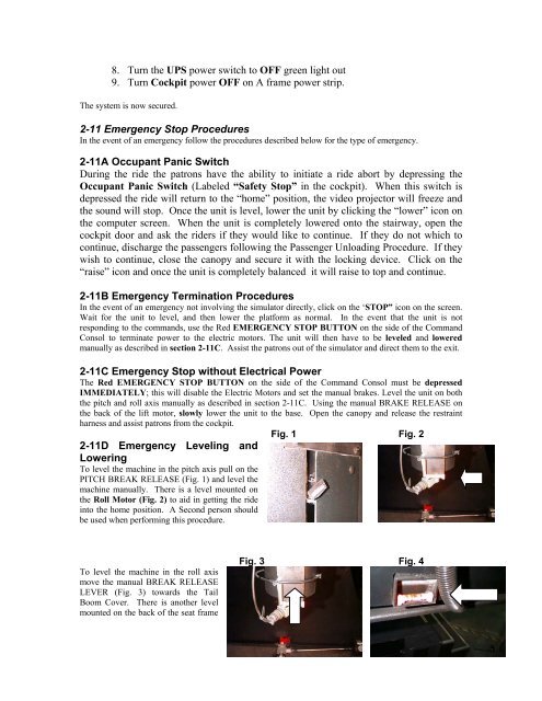
Fig. 1 Fig. 2<br />
2-11D Emergency Leveling and<br />
Lowering<br />
To level the machine in the pitch axis pull on the<br />
PITCH BREAK RELEASE (Fig. 1) and level the<br />
machine manually. There is a level mounted on<br />
the Roll Motor (Fig. 2) to aid in getting the ride<br />
into the home position. A Second person should<br />
be used when performing this procedure.<br />
To level the machine in the roll axis<br />
move the manual BREAK RELEASE<br />
LEVER (Fig. 3) towards the Tail<br />
Boom Cover. There is another level<br />
mounted on the back of the seat frame<br />
Fig. 3 Fig. 4