Hydro-Gear ZT-5400 transaxles manual - BIBUS France
Hydro-Gear ZT-5400 transaxles manual - BIBUS France
Hydro-Gear ZT-5400 transaxles manual - BIBUS France

You also want an ePaper? Increase the reach of your titles
YUMPU automatically turns print PDFs into web optimized ePapers that Google loves.
<strong>ZT</strong>-<strong>5400</strong> Powertrain<br />
Service and Repair Manual<br />
BLN-0014<br />
June 2011
TABLE OF CONTENTS<br />
Foreword. .............................. . . . .1<br />
Description and Operation ................. . . . .2<br />
Introduction. ............................ . . . .2<br />
Hydraulic Schematic. ..................... . . . .3<br />
External Features. ....................... . . 4-5<br />
Technical Specifications. .................. . . . .6<br />
Product Identification. ..................... . . . .6<br />
Safety ................................. . . . .7<br />
Personal Safety. ......................... . . . .7<br />
Tool Safety. . . . . . . . . . . . . . . . . . . . . . . . . . . . . . . . . .7<br />
Work Area Safety ........................ . . . .7<br />
Servicing Safety ......................... . . . .7<br />
Troubleshooting. ......................... . . . .8<br />
Service and Maintenance. ................. . . . .9<br />
External Maintenance. .................... . . . .9<br />
Service and Maintenance Procedures ........ . . . .9<br />
Fluids. ................................. . . . .9<br />
Fluid Volume and Level. ................... . . . .9<br />
Fluid Change Procedure. .................. . . .10<br />
Purging Procedures. ...................... . . .11<br />
Return To Neutral Setting. ................. . . .12<br />
2-Speed Option Settings. .................. . . .13<br />
Tear Down and Reassembly. ............... . . .14<br />
How to Use This Manual. .................. . . .14<br />
General Instructions ...................... . . .14<br />
Tools .................................. . . .15<br />
Torques. ............................... . . .15<br />
Transaxle Removal. ...................... . . .16<br />
Fan and Pulley. .......................... . . .17<br />
Axle Hub Assembly. ...................... . . .17<br />
Return to Neutral Assembly Option. .......... . . .18<br />
Control Arm Assembly .................... . . .19<br />
Filter And Filter Cover. .................... . . .20<br />
Brake Assembly ......................... . . .21<br />
2-Speed Arm. ........................... . . .22<br />
Bypass Actuator ......................... . . .23<br />
<strong>ZT</strong>-<strong>5400</strong> Powertrain<br />
Side Housing. ........................... . . .24<br />
Axle Shaft And Planetary <strong>Gear</strong> Set .......... . . .25<br />
Charge Pump And Oil Tube ................ . . .26<br />
Input Shaft. ............................. . . .27<br />
Swashplate. ............................ . . .28<br />
Center Section. .......................... . . .29<br />
Brake Assembly And Motor Shaft. ........... . . .30<br />
Motor Cyl Block, 2-Speed Shaft & Swashplate. . . . .31<br />
Center Section And Magnet ................ . . .32<br />
Assembly After A Complete Teardown . . . . . . . . 33-34<br />
Screw Tightening Sequence. ............... . . .35<br />
Alternate Castle Nut Torque Method. ......... . . .36<br />
<strong>ZT</strong>-<strong>5400</strong> Powertrain Exploded View . . . . . . . . . 38-39<br />
Glossary of Terms . . . . . . . . . . . . . . . . . . . . . . . . 40-41<br />
Notes. ................................. 42-43<br />
i
FOREWORD<br />
Headquartered in Sullivan, Illinois,<br />
<strong>Hydro</strong>-<strong>Gear</strong> is a world leader in the design,<br />
manufacture, and service of quality hydrostatic<br />
<strong>transaxles</strong> for the lawn and garden industry.<br />
The mission of our company is to be recognized<br />
by our customers and the industry as a<br />
world-class supplier and the quality leader in<br />
everything we do.<br />
This Service and Repair Manual is designed<br />
to provide information useful in servicing and<br />
troubleshooting the <strong>Hydro</strong>-<strong>Gear</strong> ® <strong>ZT</strong>-<strong>5400</strong><br />
Powertrain.<br />
Also included is a glossary of terms that are<br />
frequently used throughout the industry and in<br />
<strong>Hydro</strong>-<strong>Gear</strong> service publications. Understanding<br />
terminology is very important!<br />
Internal repair procedures require that the<br />
transaxle unit be removed from the vehicle.<br />
This is not a certification, test or study guide for<br />
a certification test. If a technician is interested<br />
in certification, they should contact an agent<br />
representing the EETC (Equipment and Engine<br />
Training Council) at (262) 367-6700 or their<br />
<strong>Hydro</strong>-<strong>Gear</strong> Central Service Distributor. Many<br />
distributors will be hosting certification testing.<br />
These study guides will cover most of the products<br />
and manufacturers in our industry.<br />
For more information about <strong>Hydro</strong>-<strong>Gear</strong> or our<br />
products, please contact your Central Service<br />
Distributor, or call our Customer Service Department<br />
at (217) 728-2581.<br />
It is necessary, and a good shop practice, that<br />
your service area be equipped with the proper<br />
tools and the mechanics be supplied the latest<br />
information available. All repair procedures<br />
illustrated in this guide are suggested, but preferred<br />
methods of repair.<br />
<strong>ZT</strong>-<strong>5400</strong> Powertrain 1
DESCRIPTION AND OPERATION<br />
INTRODUCTION<br />
The purpose of this <strong>manual</strong> is to provide information<br />
useful in servicing the <strong>Hydro</strong>-<strong>Gear</strong>®<br />
<strong>ZT</strong>-<strong>5400</strong> Powertrain <strong>Hydro</strong>static Transaxle.<br />
This <strong>manual</strong> includes the <strong>ZT</strong>-<strong>5400</strong> Powertrain’s<br />
general description, hydraulic schematic, technical<br />
specifications, servicing and troubleshooting<br />
procedures.<br />
Should servicing be required, the exterior of the<br />
transaxle will need to be thoroughly cleaned<br />
before beginning most procedures. Do not<br />
wash the transaxle while it is hot. Do not use<br />
a pressure washer to clean the unit.<br />
GENERAL DESCRIPTION<br />
The <strong>ZT</strong>-<strong>5400</strong> Powertrain is a self contained unit<br />
designed for the transfer and control of power.<br />
It provides an infinitely variable speed range<br />
between zero and maximum in both forward<br />
and reverse modes of operation.<br />
The <strong>ZT</strong>-<strong>5400</strong> Powertrain has a self contained<br />
fluid supply and an internal filter. The fluid is<br />
forced through the filter by a positive “head” on<br />
the fluid in the housing/expansion tank with an<br />
assist by the negative pressure created in the<br />
pump pistons as they operate.<br />
The check valves in the center section are used<br />
to control the makeup flow of the fluid to the low<br />
pressure side of the loop.<br />
A hydraulic bypass is utilized in the <strong>ZT</strong>-<strong>5400</strong><br />
Powertrain to permit moving the vehicle for a<br />
short distance at a maximum of 2 m.p.h. (3.2<br />
Km/h) without starting the engine.<br />
The <strong>ZT</strong>-<strong>5400</strong> Powertrain utilizes an internal inline<br />
floating disc brake controlled by a “cam”<br />
style actuating arm.<br />
This transaxle uses a variable displacement<br />
pump with a maximum displacement of 16.4cc<br />
per revolution, and the motor has two distinct<br />
displacement of 28.1cc and 15.0cc per revolution.<br />
The variable displacement pump features<br />
a trunnion mounted swashplate with a directproportional<br />
displacement control. Reversing<br />
the direction of the swashplate reverses the<br />
flow of oil from the pump and thus reverses<br />
the direction of the motor output rotation. The<br />
pump and motor are of the axial piston design<br />
and utilize spherical nosed pistons which are<br />
held against a thrust race by internal compression<br />
springs.<br />
2 <strong>ZT</strong>-<strong>5400</strong> Powertrain
DESCRIPTION AND OPERATION (CONTINUED)<br />
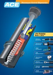
HYDRAULIC SCHEMATIC<br />
Figure 1 is a schematic of the hydraulic oil<br />
circuit. The oil supply for the hydraulic system<br />
of the <strong>ZT</strong>-<strong>5400</strong> Powertrain is also utilized for<br />
lubricating the components of the final drive<br />
assembly.<br />
The input shaft and pump cylinder block are<br />
turned in one direction only by the engine/drive<br />
belt/pulley combination. Output of the oil flow is<br />
controlled by the direction and amount that the<br />
variable swashplate is angled. As the pump pistons<br />
compress they force the oil to flow through<br />
one of two passageways (forward or reverse) in<br />
the center section to the motor cylinder block<br />
and motor shaft. Since the motor has a fixed<br />
displacement angle it is forced to turn with the<br />
flow of oil. As the angle of the pump swashplate<br />
is increased the amount of oil being pumped will<br />
increase and cause a higher speed output of the<br />
motor. Reversing the angle of the swashplate<br />
will reverse the direction of oil flow.<br />
During the operation of the transaxle, fluid<br />
is “lost” from the hydraulic loop through leak<br />
paths designed into the product for lubrication<br />
purposes (around pistons, under the rotating<br />
cylinder blocks, etc.). This “lost” fluid returns<br />
to the transaxle housing, then is pulled back<br />
into one of the check valves depending upon<br />
the direction of vehicle operation. All of this<br />
oil must pass through an internal filter.<br />
The motor cylinder block mounts onto a splined<br />
motor shaft which drives the gear train.<br />
The bypass feature in the <strong>ZT</strong>-<strong>5400</strong> Powertrain<br />
has a mechanical lever which lifts the check<br />
valves off their seat. This allows oil to flow freely<br />
between system passages in the filtered, oil<br />
filled charge galley.<br />
PUMP INPUT<br />
SHAFT<br />
PUMP<br />
VENT<br />
EXPANSION/RESERVOIR TANK<br />
SYSTEM CHECK VALVE<br />
WITH RELIEF<br />
MOTOR<br />
OUTPUT<br />
SHAFT<br />
MOTOR<br />
CHARGE<br />
RELIEF<br />
VALVE<br />
BYPASS<br />
FILTER<br />
CHARGE PUMP<br />
Figure 1, Hydraulic Schematic With Charge Pump<br />
<strong>ZT</strong>-<strong>5400</strong> Powertrain 3
EXTERNAL FEATURES <strong>ZT</strong>-<strong>5400</strong> POWERTRAIN<br />
TWO SPEED ARM (OPTIONAL)<br />
INPUT SHAFT<br />
BRAKE ARM<br />
EXPANSION TANK PORT<br />
FILTER CAP<br />
OIL COOLER PORT (OPTIONAL)<br />
BYPASS ACTUATOR<br />
— Inboard View—<br />
OIL FILL VENT PORT<br />
CHARGE PUMP<br />
— Bottom View—<br />
4 <strong>ZT</strong>-<strong>5400</strong> Powertrain
EXTERNAL FEATURES <strong>ZT</strong>-<strong>5400</strong> POWERTRAIN<br />
EXPANSION TANK PORT/FILL PORT<br />
OIL FILL VENT PORT<br />
— Top View—<br />
INPUT SHAFT<br />
INPUT SHAFT<br />
CONTROL ARM<br />
RTN<br />
Control Arm<br />
— Outboard View—<br />
Return to Neutral<br />
<strong>ZT</strong>-<strong>5400</strong> Powertrain 5
TECHNICAL SPECIFICATIONS<br />
<strong>ZT</strong>-<strong>5400</strong> Powertrain TECHNICAL SPECIFICATIONS<br />
<strong>ZT</strong>-<strong>5400</strong> Powertrain Reduction Package 0401 0402<br />
Overall Transaxle Reduction<br />
Normal Speed<br />
(Optional) 2 Speed<br />
19.0:1<br />
12.9:1<br />
23.6:1<br />
16.0:1<br />
Input Speed<br />
Maximum<br />
Minimum<br />
3600 rpm<br />
1800 rpm<br />
Output Torque<br />
Peak<br />
Continuous<br />
680 lb-ft (921 N-m)<br />
197 lb-ft (267 N-m)<br />
835 lb-ft (1132 N-m)<br />
234 lb-ft (317 N-m)<br />
Weight on Tires (per unit)<br />
Maximum with 23” tires<br />
Maximum with 24” tires<br />
Axle Shaft End Options<br />
Parking Brake Type<br />
Weight of Unit<br />
800 lb (362.8 kg)<br />
668 lb (302.9 kg)<br />
4 Bolt Flange<br />
5 Bolt Flange<br />
Internal Disc<br />
55 lb (24.9) kg<br />
PRODUCT IDENTIFICATION<br />
The model and configuration of the <strong>ZT</strong>-<strong>5400</strong> Powertrain can be determined from the label shown<br />
below.<br />
HYDRO-GEAR<br />
BOM Model Number<br />
1015-1001R 1015-1001R<br />
Sales Drawing Number<br />
Year Built<br />
8 275 F1 476 -001<br />
Assembled in USA<br />
Date (Julian- Day of year)<br />
Serial Number (unique for that model - for that day)<br />
Type of Product and Build Information<br />
Figure 2, Configuration Label<br />
6 <strong>ZT</strong>-<strong>5400</strong> Powertrain
SAFETY<br />
This symbol points out important safety<br />
instructions which, if not followed, could endanger<br />
the personal safety and/or property of<br />
yourself and others. Read and follow all instructions<br />
in this <strong>manual</strong> before attempting maintenance<br />
on your transaxle. When you see this<br />
symbol - HEED ITS WARNING.<br />
WARNING<br />
POTENTIAL FOR SERIOUS INJURY<br />
Inattention to proper safety, operation, or<br />
maintenance procedures could result in<br />
personal injury, or damage to the equipment.<br />
Before servicing or repairing the<br />
<strong>ZT</strong>-<strong>5400</strong> Powertrain transaxle, fully<br />
read and understand the safety precautions<br />
described in this section.<br />
PERSONAL SAFETY<br />
Certain safety precautions must be observed<br />
while servicing or repairing the <strong>ZT</strong>-<strong>5400</strong> Powertrain.<br />
This section addresses some of these<br />
precautions but must not be considered an<br />
all-inclusive source on safety information. This<br />
section is to be used in conjunction with all other<br />
safety material which may apply, such as:<br />
1. Other <strong>manual</strong>s pertaining to this machine,<br />
2. Local and shop safety rules and codes,<br />
3. Governmental safety laws and regulations.<br />
Be sure that you know and understand the<br />
equipment and the hazards associated with it.<br />
Do not place speed above safety.<br />
Notify your supervisor whenever you feel there<br />
is any hazard involving the equipment or the<br />
performance of your job.<br />
Never allow untrained or unauthorized personnel<br />
to service or repair the equipment.<br />
Wear appropriate clothing. Loose or hanging<br />
clothing or jewelry can be hazardous. Use the<br />
appropriate safety equipment, such as eye<br />
and hearing protection, and safety-toe and<br />
slip-proof shoes.<br />
Never use compressed air to clean debris from<br />
yourself or your clothing.<br />
TOOL SAFETY<br />
Use the proper tools and equipment for the<br />
task.<br />
Inspect each tool before use and replace any<br />
tool that may be damaged or defective.<br />
WORK AREA SAFETY<br />
Keep the work area neat and orderly. Be sure<br />
it is well lit, that extra tools are put away, trash<br />
and refuse are in the proper containers, and dirt<br />
or debris have been removed from the working<br />
areas of the machine.<br />
The floor should be clean and dry, and all extension<br />
cords or similar trip hazards should be<br />
removed.<br />
SERVICING SAFETY<br />
Certain procedures may require the vehicle to<br />
be disabled in order to prevent possible injury<br />
to the servicing technician and/or bystanders.<br />
The loss of hydrostatic drive line power may<br />
result in the loss of hydrostatic braking capability.<br />
Some cleaning solvents are flammable. Use<br />
only approved cleaning materials: Do not use<br />
explosive or flammable liquids to clean the<br />
equipment.<br />
To avoid possible fire, do not use cleaning<br />
solvents in an area where a source of ignition<br />
may be present.<br />
Discard used cleaning material in the appropriate<br />
containers.<br />
<strong>ZT</strong>-<strong>5400</strong> Powertrain 7
TROUBLESHOOTING<br />
WARNING<br />
Do not attempt any servicing or adjustments<br />
with the engine running.<br />
Use extreme caution while inspecting<br />
the drive belt assembly and all vehicle<br />
linkage!<br />
Follow all safety procedures outlined in<br />
the vehicle owner’s <strong>manual</strong>.<br />
In many cases, problems with the <strong>ZT</strong>-<strong>5400</strong><br />
Powertrain are not related to a defective<br />
transaxle, but are caused by slipping drive belts,<br />
partially engaged bypass valves, and loose or<br />
damaged control linkages. Be sure to perform<br />
all operational checks and adjustments outlined<br />
in Service and Maintenance, before assuming<br />
the transaxle is malfunctioning. The table below<br />
provides a troubleshooting checklist to help<br />
determine the cause of operational problems.<br />
TROUBLESHOOTING CHECKLIST<br />
Possible Cause<br />
Corrective Action<br />
Unit Operates In One Direction Only<br />
Control linkage bent or out of adjustment Repair or replace linkage, Page 9<br />
Drive belt slipping or pulley damaged Repair or replace drive belt or pulley, Page 9<br />
Vehicle Does Not Drive/Track Straight<br />
Vehicle tires improperly inflated<br />
Refer to vehicle manufacturer suggested pressure<br />
Control linkage bent or out of adjustment Repair or replace linkage, Pages 9 and 12<br />
Bypass assembly sticking Repair or replace bypass, Page 23<br />
Brake Partially Engage<br />
Disengage Brake, Replace Broken or Missing Brake Return Spring<br />
Unit Is Noisy<br />
Oil level low or contaminated oil Fill to proper level or change oil, Page 10<br />
Excessive loading Reduce vehicle loading, Page 9<br />
Loose parts<br />
Repair or replace loose parts<br />
Bypass assembly sticking Repair or replace linkage, Page 9<br />
Air trapped in hydraulic system Purge hydraulic system, Page 11<br />
Brake Partially Engage<br />
Disengage Brake, Replace Broken or Missing Brake Return Spring<br />
Unit Has No/Low Power<br />
Engine speed low<br />
Adjust to correct setting<br />
Control linkage bent or out of adjustment Repair or replace linkage, Page 9<br />
Drive belt slipping or pulley damaged Repair or replace drive belt or pulley, Page 9<br />
Oil level low or contaminated oil Fill to proper level or change oil, Page 10<br />
Excessive loading Reduce vehicle loading, Page 9<br />
Bypass assembly sticking Repair or replace linkage, Page 9<br />
Air trapped in hydraulic system Purge hydraulic system, Page 11<br />
Brake Partially Engage<br />
Disengage Brake, Replace Broken or Missing Brake Return Spring<br />
Unit Is Operating Hot<br />
Debris buildup around transaxle Clean off debris, Page 9<br />
Cooling fan damaged Repair or replace cooling fan, Pages 17<br />
Oil level low or contaminated oil Fill to proper level or change oil, Page 10<br />
Excessive loading Reduce vehicle loading, Page 9<br />
Air trapped in hydraulic system Purge hydraulic system, Page 11<br />
Brake Partially Engage<br />
Disengage Brake, Replace Broken or Missing Brake Return Spring<br />
Transaxle Leaks Oil<br />
Damaged seals, housing, or gaskets<br />
Replace damaged components<br />
Air trapped in hydraulic system Purge hydraulic system, Page 11<br />
8 <strong>ZT</strong>-<strong>5400</strong> Powertrain
SERVICE AND MAINTENANCE<br />
NOTE: Any servicing dealer attempting a<br />
warranty repair must have prior<br />
approval before conducting maintenance<br />
of a <strong>Hydro</strong>-<strong>Gear</strong>® product<br />
unless the servicing dealer is a current<br />
Authorized <strong>Hydro</strong>-<strong>Gear</strong> Service<br />
Center.<br />
EXTERNAL MAINTENANCE<br />
Regular external maintenance of the <strong>ZT</strong>-<strong>5400</strong><br />
Powertrain should include the following:<br />
1. Check the vehicle operator’s <strong>manual</strong> for<br />
the recommended load ratings. Insure<br />
the current application does not exceed<br />
load rating.<br />
2. Check oil level in accordance with Figure 3<br />
Page 10.<br />
3. Inspect the vehicle drive belt, idler pulley(s),<br />
and idler spring(s). Insure that no belt<br />
slippage can occur. Slippage can cause low<br />
input speed to the transmission.<br />
4. Inspect the transmission cooling fan for<br />
broken or distorted blades and remove any<br />
obstructions (grass clippings, leaves, dirt,<br />
etc.).<br />
5. Inspect the parking brake and vehicle<br />
linkage to insure proper actuation and<br />
adjustment of the parking brake.<br />
6. Inspect the vehicle control linkage to the<br />
directional control arm on transaxle. Also,<br />
insure the control arm is securely fastened<br />
to the trunnion arm of the transaxle.<br />
7. Inspect the bypass mechanism on the<br />
transaxle and vehicle linkage to insure it<br />
actuates and releases fully.<br />
SERVICE AND MAINTENANCE<br />
PROCEDURES<br />
All the service and maintenance procedures<br />
presented on the following pages can be<br />
performed while the <strong>ZT</strong>-<strong>5400</strong> Powertrain is<br />
mounted on the vehicle. Any repair procedures<br />
as mentioned in the tear down and assembly<br />
section of this <strong>manual</strong> must be performed after<br />
the unit has been removed from the vehicle.<br />
FLUIDS<br />
The fluids used in <strong>Hydro</strong>-<strong>Gear</strong> products have<br />
been carefully selected, and only equivalent, or<br />
better products should be substituted.<br />
Typically, an engine oil with a minimum rating<br />
of 9.0 cSt (55 SUS) at 230°F (110° C) and an API<br />
classification of SL is recommended. A 20W-50<br />
engine oil has been selected for use by the factory<br />
and is recommended for normal operating<br />
temperatures. Biodegradable oils are not approved<br />
for this unit as they degrade too quickly<br />
while in service.<br />
FLUID VOLUME AND LEVEL<br />
Fluid volume information is provided in the<br />
Table below.<br />
Certain situations may require additional fluid<br />
to be added or even replaced. Refer to Page<br />
10, Figure 3 and page 5 for the proper fill port<br />
location.<br />
Fill the <strong>ZT</strong>-<strong>5400</strong> Powertrain to the top of the oil<br />
fill port.<br />
Recheck the fluid level once the unit has been<br />
operated for approximately 1 minute.<br />
Purging may be required. Refer to the purging<br />
procedures on page 11.<br />
<strong>ZT</strong>-<strong>5400</strong> Powertrain 9
FLUID CHANGE PROCEDURE<br />
This transaxle is designed with a serviceable<br />
filter. To ensure constant fluid quality levels and<br />
longer life, an initial oil and filter change at 100<br />
hours is recommended. Subsequent changes<br />
are recommended at 400 hour intervals minimum,<br />
or yearly, whichever comes first.<br />
The following procedure can be performed with<br />
the transaxle installed in the vehicle, and the<br />
vehicle on level ground. Apply the bypass valve<br />
and lock the vehicle parking brake.<br />
Oil Fill Volume<br />
(Fill to 100% capacity)<br />
1. Place an oil drain pan (12” or more in diam<br />
ter and 8 qt. capacity is optimal) beneath the<br />
oil filter. Remove the oil filter cover from the<br />
transaxle to drain the oil. Remove the O-ring<br />
from the cover and discard the O-ring.<br />
2. After the oil has drained from the transaxle,<br />
remove the oil filter from the transaxle housing.<br />
3. Install a new filter (<strong>Hydro</strong>-<strong>Gear</strong> part number<br />
71943). Install a new O-ring onto the filter<br />
cover and install the filter cover. See Figure<br />
3a. See page 15 for torque specifications.<br />
4. Remove the top oil fill vent port plug (see<br />
page 5) and fill the transaxle with new<br />
20W50 motor oil through the expansion<br />
tank port/fill port until oil reaches the oil fill<br />
vent port.<br />
5. Install the top oil fill vent port plug and continue<br />
filling the system with oil until the fill<br />
line is reached in the expansion tank.<br />
6. Drain old oil filter of all free flowing oil prior<br />
to disposal. Place used oil in appropriate<br />
containers and deliver to an approved recycling<br />
collection facility.<br />
Oil Volume = 4875 - 4925 mL<br />
(164.8 - 166.5 fl. oz.)<br />
(1.287 - 1.301 gal.)<br />
Note: The oil volume figure shown does not<br />
include what is in the expansion tank<br />
hose or the expansion tank. That will<br />
have to be determined by the machine<br />
manufacturer/end user due to varying<br />
hose sizes/lengths and expansion tank<br />
sizes.<br />
Filter<br />
Figure 3, Oil Volume<br />
7. Proceed to the purge procedure.<br />
O-ring<br />
Filter cover<br />
Figure 3a, Filter Components<br />
10 <strong>ZT</strong>-<strong>5400</strong> Powertrain
PURGING PROCEDURES<br />
Due to the effects air has on efficiency in<br />
hydrostatic drive applications, it is critical that<br />
it be purged from the system.<br />
These purge procedures should be implemented<br />
any time a hydrostatic system has<br />
been opened to facilitate maintenance or any<br />
additional oil has been added to the system.<br />
Air creates inefficiency because its compression<br />
and expansion rate is higher than that of<br />
the oil approved for use in hydrostatic drive<br />
systems.<br />
The resulting symptoms in hydrostatic systems<br />
may be:<br />
1. Noisy operation.<br />
2. Lack of power or drive after short term<br />
operation.<br />
3. High operation temperature and excessive<br />
expansion of oil.<br />
Before starting, make sure the transaxle/transmission<br />
is at the proper oil level. If it is not, fill<br />
to the specifications outlined on page 9.<br />
The following procedures should be performed<br />
with the vehicle drive wheels off the ground,<br />
then repeated under normal operating conditions.<br />
1. With the bypass valve open and the engine<br />
running, slowly move the directional control<br />
in both forward and reverse directions<br />
(5 to 6 times), as air is purged from the unit,<br />
the oil level will drop.<br />
2. With the bypass valve closed and the<br />
engine running, slowly move the directional<br />
control in both forward and reverse<br />
directions (5 to 6 times). Check the oil level,<br />
and add oil as required after stopping<br />
engine.<br />
3. It may be necessary to repeat Steps 1 and 2<br />
until all the air is completely purged from the<br />
system. When the transaxle moves forward<br />
and reverse at normal speed purging is<br />
complete.<br />
<strong>ZT</strong>-<strong>5400</strong> Powertrain 11
RETURN TO NEUTRAL SETTING<br />
WARNING<br />
POTENTIAL FOR SERIOUS INJURY<br />
Certain procedures require the vehicle engine<br />
to be operated and the vehicle to be raised off<br />
the ground. To prevent possible injury to the servicing<br />
technician and/or bystanders, insure the<br />
vehicle is properly secured.<br />
The return to neutral mechanism on the transaxle<br />
is designed to set the directional control into<br />
a neutral position when the operator removes<br />
their hand from the control lever. Follow the<br />
procedures below to properly adjust the return<br />
to neutral mechanism on the transaxle:<br />
1. Confirm the transaxle is in the operating mode<br />
(bypass disengaged). Raise the vehicle’s drive<br />
tires off the ground to allow free rotation.<br />
NOTE: It may be necessary to remove the<br />
drive tire from the axle hub to access<br />
the linkage control and the transaxle<br />
return arm.<br />
2. Remove the Original Equipment Manufacturer’s<br />
(OEM’s) control linkage at the control<br />
arm.<br />
3. Start the engine and increase the throttle to<br />
full engine speed.<br />
4. Check for axle rotation. If the axles do not<br />
rotate, go to Step 5. If the axles rotate, go<br />
to Step 6.<br />
5. Stop the vehicle’s engine. Reattach and<br />
adjust the OEM linkage according to the<br />
OEM <strong>manual</strong>. Recheck according to Step<br />
3 and 4. Start the vehicle engine.<br />
6. Note the axle directional movement. Stop<br />
the vehicle engine. Loosen the lock down<br />
screw (61) until the control arm (54) can<br />
be rotated. Rotate the control arm in the<br />
opposite direction of the wheel rotation 5<br />
degrees. Tighten the lock down screw. Recheck<br />
according to steps 3 and 4. Refer to<br />
Figure 4.<br />
61<br />
54<br />
Figure 4, Return to Neutral<br />
12 <strong>ZT</strong>-<strong>5400</strong> Powertrain
2-SPEED OPTION SETTING<br />
WARNING<br />
POTENTIAL FOR SERIOUS INJURY<br />
Certain procedures require the vehicle engine<br />
to be operated and the vehicle to be raised off<br />
the ground. To prevent possible injury to the servicing<br />
technician and/or bystanders, insure the<br />
vehicle is properly secured.<br />
The 2-speed option mechanism on the transaxle<br />
is designed to increase the axle speed when<br />
the 2-speed control arm (168) is moved from<br />
its vertical position. Follow the procedure below<br />
to properly set the 2-speed option on the<br />
transaxle:<br />
Note: THIS PROCEDURE SHOULD ONLY<br />
HAVE TO BE DONE IF THE THE LOCK<br />
DOWN ARM (165) NEEDS REPLACED<br />
OR A NEW SIDE HOUSING HAS TO BE<br />
INSTALLED. IT IS NOT NECESSARY TO<br />
EVER REMOVE THE LOCK DOWN ARM<br />
(165) FOR ANY OTHER REASON DURING<br />
THE DISASSEMBLY OF THIS UNIT.<br />
1. Confirm the transaxle is in the operating<br />
mode (bypass disengaged). Raise the<br />
vehicle’s drive tires off the ground to allow<br />
free rotation.<br />
Note: It may be necessary to remove the<br />
drive tire from the axle hub to access<br />
the linkage control.<br />
2. Remove the Original Equipment Manufacturer’s<br />
(OEM’s) control linkage at the 2-speed<br />
control arm (168). Position the 2-speed<br />
control arm (168) so it is in the normal speed<br />
(vertical) position. Refer to Figure 5.<br />
3. Start the engine and increase the throttle to<br />
full engine speed.<br />
4. Stroke the transaxle control arm (54) until<br />
183 rpm axle speed is obtained. Refer to<br />
Figure 6.<br />
5. Rotate the 2-speed control arm (168) and<br />
lock down arm (165) together until the<br />
axle speed reaches 265 rpm. Lock down<br />
the 2-speed lock down arm (165) with the<br />
2-speed control arm (168) against the<br />
stop.<br />
6. Stop the engine and reconnect any OEM<br />
linkage.<br />
168<br />
54<br />
165<br />
Figure 5, 2-Speed Control Arm<br />
Figure 6, Transaxle Control Arm<br />
<strong>ZT</strong>-<strong>5400</strong> Powertrain 13
TEAR DOWN AND REASSEMBLY<br />
HOW TO USE THIS MANUAL<br />
Each subassembly illustrated in this section<br />
is illustrated by an exploded view showing<br />
the parts involved. The item reference numbers<br />
in each illustration are for assembly<br />
instructions only. See page 37 for part names<br />
and descriptions. A complete exploded view<br />
and item list of the transaxle is provided on<br />
pages 38 and 39.<br />
Many of the parts and subassemblies of this<br />
transaxle can be removed and serviced independently<br />
of other components. Where some<br />
components and assemblies must be removed<br />
before a given assembly can be serviced, that<br />
information is given at the beginning of the<br />
disassembly instructions.<br />
GENERAL INSTRUCTIONS<br />
Cleanliness is a primary means of assuring<br />
satisfactory life on repaired units. Thoroughly<br />
clean all exposed surfaces prior to any type<br />
of maintenance. Cleaning of all parts by using<br />
a solvent wash and air drying is usually<br />
adequate. As with any precision equipment, all<br />
parts must be kept free of foreign material and<br />
chemicals.<br />
Protect all exposed sealing surfaces and open<br />
cavities from damage and foreign material. The<br />
external surfaces should be cleaned before<br />
beginning any repairs.<br />
Upon removal, it is recommended that all seals,<br />
O-rings, and gaskets be replaced. During<br />
installation lightly lubricate all seals, O-rings,<br />
gaskets with a clean petroleum jelly prior to<br />
assembly. Also protect the inner diameter of<br />
seals by covering the shaft with a cellophane<br />
(plastic wrap, etc.) material. Be sure all remnants<br />
of this covering are removed after servicing.<br />
Parts requiring replacement must be replaced<br />
from the appropriate kits identified in the Items<br />
Listing, found on page 39. Use only original<br />
<strong>Hydro</strong>-<strong>Gear</strong>® replacement parts found listed in<br />
in the authorized dealer section of the <strong>Hydro</strong>-<br />
<strong>Gear</strong> web site (www.hydro-gear.com).<br />
IMPORTANT: When internal repair is performed<br />
on the <strong>ZT</strong>-<strong>5400</strong> Powertrain, the filter assembly<br />
must be replaced.<br />
TRANSAXLE REMOVAL<br />
It is necessary to remove the <strong>ZT</strong>-<strong>5400</strong> Powertrain<br />
from the vehicle before performing the repair<br />
procedures presented in this section.<br />
LIMITED DISASSEMBLY<br />
The following procedures are presented in<br />
the order in which they must be performed to<br />
completely disassemble the unit. Do not<br />
disassemble the unit any farther than is<br />
necessary to accomplish the required repairs.<br />
Each disassembly procedure is followed by a<br />
corresponding assembly procedure.<br />
Reassembly is accomplished by performing<br />
the “Assembly” portions of the procedures. If<br />
the unit has been completely disassembled, a<br />
summary of the assembly procedures, in the<br />
order in which they should occur, is given on<br />
page 33.<br />
Anytime the tapered axle hub is removed it<br />
should be replaced by a new axle hub, insuring<br />
that the integrity of the taper lock is not lost.<br />
14 <strong>ZT</strong>-<strong>5400</strong> Powertrain
TOOLS<br />
REQUIRED TOOLS<br />
Miscellaneous<br />
2 Screw Drivers 33 mm socket<br />
3/8” Drive Ratchet 1/2” socket<br />
Rubber Mallet<br />
3/4” socket<br />
Large External Retaining Ring Pliers<br />
9/16” socket<br />
Large Internal Retaining Ring Pliers<br />
7/8” socket<br />
Small External Retaining Ring Pliers<br />
13/16” socket<br />
Small Internal Retaining Ring Pliers<br />
15/16” socket<br />
AN-04 (1/8 Allen)<br />
1 1/8” socket<br />
AN-06 (3/16 Allen)<br />
1 7/16” socket<br />
AN-08 (1/4 Allen)<br />
AN-10 (5/16 Allen)<br />
AN-12 (3/8 Allen)<br />
T-25 Torx<br />
T-40 Torx<br />
3 Jaw Puller<br />
Sockets<br />
TORQUES As a general rule, use the low end of the torque spec on fasteners when reassembling the unit.<br />
REQUIRED TORQUE VALUES<br />
Item Description Torque Operation<br />
6 HFHCS 230-290 in-lbs [25.9-32.7 Nm] Housing screw<br />
21 Bolt, Hex Flange 450-550 in-lbs [50.8-62.1 Nm] Center Section<br />
22 Bolt, Hex Flange 450-550 in-lbs [50.8-62.1 Nm] Center Section<br />
26 Seat Check Nut 280-400 in-lbs [31.6-45.2 Nm] Center Section<br />
30 Check Spring Retainer 200-250 in-lbs [ 22.59-28.24 Nm] Center Section<br />
36 Plug 200-265 in-lbs [ 22.59-29.95 Nm] Center Section<br />
40 Bolt, Self Tapping 20-30 in-lbs [ 2.25-3.38 Nm] Center Section Magnet<br />
52 Stud 50-120 in-lbs [5.7-13.5 Nm] RTN<br />
56 TWHCS 230-310 in-lbs [25.9-30.0 Nm] RTN<br />
57 Nut 85-120 in-lbs [9.6-13.5 Nm] RTN<br />
61 SHCS 175-200 in-lbs [19.7-22.5 Nm] RTN<br />
67 Screw 175-200 in-lbs [19.7-22.5 Nm] RTN<br />
113 Castle Nut* 275-350 ft-lbs* [ 372.9-474.5 Nm] Hub<br />
126 Nut 660-800 in-lbs [74.5-90.3 Nm] Brake Shaft<br />
145 Screw 80-120 in-lbs [9.0-13.5 Nm] Gerotor Cover<br />
152 Plug, Oil Filter Cover 480-580 in-lbs [54.23-65.53 Nm] Oil Filter<br />
167 Screw 175-200 in-lbs [19.7-22.5 Nm] Two Speed<br />
170 Plug Metal 200-280 in-lbs [22.5-31.6 Nm] Exspansion Tank/Fill Port<br />
171/173 Plug 32-42 in-lbs [3.6-4.7 Nm] Oil Fill Vent Port<br />
172 Plug, Metal 200-280 in-lbs [22.5-31.6 Nm] Exspansion Tank Port<br />
174 Plug Metal 110-150 in-lbs [12.4-16.9 Nm] External Cooler Port Plug<br />
183 Nut, HEX, 1/2-20 W/ PATCH 540-660 in-lbs [61.6- 74.6Nm] Fan/Pully<br />
* If a 275 ft-lbs torque wrench is not available please use the alternative torque procedure outlined on page 36.<br />
<strong>ZT</strong>-<strong>5400</strong> Powertrain 15
TRANSAXLE REMOVAL<br />
NOTE: It is necessary to remove the <strong>ZT</strong>-<strong>5400</strong><br />
Powertrain from the vehicle before<br />
performing the repair procedures presented<br />
in this section.<br />
Before starting any disassembly, make<br />
certain that your work area is neat and<br />
clean. Clean the external parts of the<br />
transaxle.<br />
The following procedures are presented<br />
in the order recommended for a<br />
complete tear down of the transaxle.<br />
Do not disassemble the unit any farther<br />
than necessary to accomplish the<br />
required repairs.<br />
Reassembly is accomplished by performing<br />
the “Assembly” portions of the<br />
procedures. If the unit has been completely<br />
disassembled, a summary of<br />
the assembly procedures, in the order<br />
in which they should occur, is given on<br />
page 33.<br />
Figure 7, <strong>ZT</strong>-<strong>5400</strong> Powertrain Transaxle<br />
16 <strong>ZT</strong>-<strong>5400</strong> Powertrain
FAN AND PULLEY<br />
Refer to Figure 8<br />
1. Remove the locknut (183) and the washer<br />
(182).<br />
2. Remove the fan (181) and the washer<br />
(184).<br />
3. Remove the pulley assembly (180).<br />
Assembly<br />
1. Reassemble all parts in the reverse order<br />
of disassembly.<br />
2. When tightening the lock nut (183), refer to<br />
the table on page 15 for the required torque<br />
values.<br />
183<br />
182<br />
AXLE HUB ASSEMBLY<br />
Refer to Figure 8<br />
1. Remove the axle cap and discard (114).<br />
2. Remove the cotter pin and discard (116).<br />
3. Remove the castle nut (113).<br />
4. Remove the taper hub assembly (111) and<br />
discard.<br />
NOTE: A new hub will have to be ordered<br />
to replace the discarded hub.<br />
5. Remove the axle cover (115).<br />
6. Remove the axle shaft key (110).<br />
Inspection<br />
1. Check all components for excessive wear<br />
or damage. Replace if necessary.<br />
Assembly<br />
181<br />
1. Reassemble all parts in the reverse order<br />
of disassembly.<br />
184<br />
180<br />
2. When tightening the castle nut (113)*, refer<br />
to the table on page 15 for the required<br />
torque values.<br />
NOTE: As a general rule, use the low end of the<br />
torque specification . Once at the specified<br />
torque, rotate castle nut clockwise<br />
to align with nearest cotter pin hole.<br />
110<br />
*SEE PAGE 36 FOR ALTERNATE<br />
TORQUE METHOD.<br />
115<br />
111<br />
113<br />
114<br />
Figure 8, Fan and Hub<br />
<strong>ZT</strong>-<strong>5400</strong> Powertrain 17<br />
116
RETURN TO NEUTRAL ASSEMBLY OPTION<br />
Refer to Figure 9<br />
Disassembly<br />
1. Remove all items previously discussed in<br />
their recommended order.<br />
2. Remove the spring (64).<br />
3. Remove the Torx head screw (56) and discard.<br />
Remove the washer (63).<br />
4. Remove the scissor arm (62). Remove the<br />
Allen head screw (61), the bushing (60) and<br />
the RTN control arm (54).<br />
5. Remove the neutral arm (59) and the spacer<br />
(58).<br />
Assembly<br />
1. Reassemble all parts in the reverse order<br />
of disassembly.<br />
2. When tightening the fasteners, refer to the<br />
table on page 15 for the required torque<br />
values.<br />
3. Install new Torx head screw (56) and lip seal<br />
(51) from seal kit.<br />
NOTE: As a general rule, use the low end of<br />
the torque specification on fasteners<br />
when reassembling the unit.<br />
NOTE: Only remove the seal (51) and the RTN<br />
control arm stroke limiter (65) if damaged<br />
or worn. Mark the orientation of<br />
the stroke limiter before removal.<br />
Inspection<br />
1. Inspect all parts for excessive wear or damage.<br />
Replace if necessary.<br />
51<br />
58<br />
59<br />
54<br />
60<br />
61<br />
65<br />
63<br />
56<br />
66<br />
67<br />
64<br />
Figure 9 Return To Neutral<br />
62<br />
18 <strong>ZT</strong>-<strong>5400</strong> Powertrain
CONTROL ARM ASSEMBLY<br />
Refer to Figure 10<br />
Disassembly<br />
1. Remove all items previously discussed in<br />
their recommended order.<br />
2. Remove the Torx head screw (56) and discard.<br />
3. Remove the nut (57) and the washer (55).<br />
4. Remove the control arm (54).<br />
5. Remove the plastic washer (53) and the<br />
stud (52).<br />
6. Remove the stop plate (65).<br />
Assembly<br />
1. Reassemble all parts in the reverse order<br />
of disassembly.<br />
2. When tightening the fasteners, refer to the<br />
table on page 15 for the required torque<br />
values.<br />
3. Install new Torx head screw (56) and lip seal<br />
(51) from seal kit.<br />
NOTE: As a general rule, use the low end of<br />
the torque specification on fasteners<br />
when reassembling the unit.<br />
NOTE: Only remove the lip seal (51) and stop<br />
plate (65) if damaged or worn, or if<br />
doing a complete disassembly. Mark<br />
the orientation of the stop plate before<br />
removal.<br />
Inspection<br />
1. Inspect all parts for excessive wear or damage.<br />
Replace if necessary.<br />
51<br />
65<br />
66<br />
67<br />
52<br />
53 54<br />
55<br />
57<br />
56<br />
Figure 10, Control Arm<br />
<strong>ZT</strong>-<strong>5400</strong> Powertrain 19
FILTER AND FILTER COVER<br />
Refer to Figure 11<br />
Disassembly<br />
1. Remove the filter cover (152).<br />
2. Remove the O-ring (151) from the cover<br />
(152) and discard.<br />
3. Remove the filter (150) and discard.<br />
Inspection<br />
1. Inspect all parts for wear or damage. Replace<br />
as necessary.<br />
Assembly<br />
1. Install the new filter (150).<br />
2. Install the new O-ring (151) onto the cover<br />
(152).<br />
3. Install the filter cover (152). Refer to torque<br />
chart on page 15.<br />
2. Check for old filter grommet stuck on the<br />
filter tube. Remove if present.<br />
152<br />
151<br />
150<br />
Figure 11, Filter and Filter Cover<br />
20 <strong>ZT</strong>-<strong>5400</strong> Powertrain
BRAKE ASSEMBLY<br />
Refer to Figure 12<br />
Disassembly<br />
1. Remove all items previously discussed in<br />
their recommended order.<br />
2. Mark the orientation of the brake arm (130)<br />
before removal.<br />
Assembly<br />
1. Reassemble all parts in the reverse order<br />
of disassembly.<br />
2. Install new seal (127) from seal kit.<br />
3. Remove the retaining ring (131) and discard.<br />
4. Remove the brake handle (130) and the<br />
bushing (128).<br />
5. Remove the seal (127) and discard.<br />
NOTE: Only remove the seal (127) if damaged<br />
or worn, or if doing a complete disassembly.<br />
Inspection<br />
1. Inspect all parts for wear or damage. Replace<br />
as necessary.<br />
131<br />
130<br />
128<br />
127<br />
Figure 12, Brake Assembly<br />
<strong>ZT</strong>-<strong>5400</strong> Powertrain 21
2–SPEED ARM (OPTIONAL)<br />
Refer to Figure 13<br />
Disassembly<br />
1. Remove all external items previously discussed<br />
in their recommended order.<br />
2. Remove the external retaining ring (169)<br />
and discard. Remove the 2-speed arm<br />
(168).<br />
NOTE: Only remove the 2-speed lock-down<br />
arm (165) if damaged. Mark the orientation<br />
before removal.<br />
3. Remove the screw (167) and the washer<br />
(166).<br />
4. Remove the 2–speed lock-down arm<br />
(165).<br />
5. Remove the seal (164) and discard.<br />
NOTE: Only remove the seal (164) if damaged<br />
or worn, or if doing a complete disassembly.<br />
Inspection<br />
1. Inspect the 2–speed actuating handle (168)<br />
and the 2–speed lock-down arm (165) for<br />
excessive wear or damage. Replace if necessary.<br />
Assembly<br />
1. Reassemble all parts in the reverse order<br />
of disassembly.<br />
2. Install the new seal (164) from seal kit.<br />
3. Install the 2–speed lock-down arm (165),<br />
washer (166) and screw (167). Refer to the<br />
table on page 15 for the required torque<br />
values.<br />
4. Install the 2-speed actuating arm (168).<br />
screw (167).<br />
5. Install the new external retaining ring<br />
(169).<br />
169<br />
168<br />
165<br />
164<br />
167<br />
166<br />
Figure 13, 2- Speed Arm<br />
22 <strong>ZT</strong>-<strong>5400</strong> Powertrain
BYPASS ACTUATOR<br />
Refer to Figure 14<br />
Disassembly<br />
1. Remove all external items previously discussed<br />
in their recommended order.<br />
2. Remove the retaining ring (45), wave spring<br />
(44) and discard; then, remove the bypass<br />
actuator rod (43).<br />
3. Remove the O-rings (42) from the bypass<br />
rod (43) and discard.<br />
4. Remove the lip seal (41) and discard.<br />
NOTE: Only remove the seal (41) if damaged<br />
or worn, or if doing a complete disassembly.<br />
Assembly<br />
1. Reassemble all parts in the reverse order<br />
of disassembly.<br />
2. Install a new lip seal (41).<br />
3. Install two new O-rings onto the actuator<br />
bypass rod.<br />
4. Install the bypass actuator rod (43).<br />
5. Install the new wave spring (44) and the new<br />
retaining ring (45).<br />
Inspection<br />
1. Inspect the actuator bypass rod (43) for<br />
wear or damage. Replace if necessary.<br />
NOTE: Take care to insure that the actuator<br />
bypass rod is free of burrs that may cut<br />
the rubber lip seal.<br />
2. Inspect the housing bore.<br />
45<br />
44<br />
43<br />
42<br />
42<br />
41<br />
Figure 14, Bypass Actuator<br />
<strong>ZT</strong>-<strong>5400</strong> Powertrain 23
SIDE HOUSING<br />
Refer to Figure 15<br />
Disassembly<br />
1. Remove all external items previously discussed<br />
in their recommended order.<br />
2. Remove the retaining ring (107), the seal<br />
(106) and discard.<br />
3. Remove the screws (6), then separate side<br />
housing (2) from main housing (1).<br />
Inspection<br />
1. Inspect the bearing and bushing areas in the<br />
side cover for excessive wear or damage.<br />
Replace if necessary.<br />
Assembly<br />
1. Reassemble all parts in the reverse order<br />
of disassembly.<br />
2. Apply a bead of sealant around the perimeter<br />
of the main housing face. See “Sealant<br />
Application Diagram” on page 34.<br />
3. Align the side housing (2) with the main<br />
housing (1). Use care not to smear the sealant<br />
bead.<br />
4. Install the seventeen housing screws (6).<br />
Refer to the screw tightening pattern on<br />
page 35.<br />
5. When tightening the fasteners, refer to the<br />
table on page 15 for the required torque<br />
values.<br />
6<br />
2<br />
6<br />
106<br />
107<br />
Figure 15, Side Housing<br />
24 <strong>ZT</strong>-<strong>5400</strong> Powertrain
AXLE SHAFT AND PLANETARY GEAR SET<br />
Refer to Figure 16, 17<br />
Disassembly<br />
1. Remove all external items previously discussed<br />
in their recommended order.<br />
NOTE: Note the location of the ring gear<br />
tabs.<br />
2. Remove the axle shaft (103) and the planetary<br />
assembly.<br />
3. Remove the axle bearing (105) and washer<br />
(104).<br />
4. Remove the axle shaft thrust ball (100) from<br />
the main house (1).<br />
Assembly<br />
1. Reassemble all parts in the reverse order<br />
of disassembly.<br />
1<br />
RING GEAR TAB<br />
PLANETARY ASSEMBLY<br />
103<br />
5. Remove the axle retaining ring (101), axle<br />
shaft spacer (102), axle gear (94), ring gear<br />
(95), planet gears (96), sun gear (97) and<br />
the carrier (98).<br />
Inspection<br />
1. Inspect all items of the planetary gear set<br />
for wear and or damage.<br />
100<br />
Figure 17, Planetary <strong>Gear</strong> Set<br />
NOTE: When installing the ring gear assembly<br />
— line up the ring gear tabs with the<br />
housing tabs.<br />
101 102 94<br />
95<br />
96<br />
97<br />
98<br />
103<br />
104<br />
105<br />
Figure 16, Planetary <strong>Gear</strong> Set<br />
<strong>ZT</strong>-<strong>5400</strong> Powertrain 25
CHARGE PUMP AND OIL TUBE<br />
Refer to Figure 18<br />
Disassembly<br />
1. Remove all external items previously discussed<br />
in their recommended order.<br />
2. Pry out the oil tube (38).<br />
3. Mark the orientation of the charge pump<br />
cover (144).<br />
4. Remove the charge cover screws (145),<br />
the cover (144) and the gerotor (142),<br />
then remove and discard the O-ring (143).<br />
5. Remove the gerotor and the charge tubes<br />
(141).<br />
6. Remove and discard the O-ring (146)<br />
Inspection<br />
Assembly<br />
1. Reassemble all parts in the reverse order<br />
of disassembly.<br />
2. When installing the charge pump cover<br />
(144) line up the mark on the cover with the<br />
mark on the housing — refer to Disassembly<br />
step 3.<br />
3. When tightening the fasteners, refer to the<br />
table on page 15 for the required torque<br />
values.<br />
4. Place a small dab of sealant on each end<br />
of the oil tube (38) just before the bend. The<br />
sealant should contact the inside of the side<br />
housing when it is installed.<br />
1. Inspect items of the charge cover assembly<br />
for wear and or damage.<br />
Replace if necessary.<br />
38<br />
146<br />
141<br />
142<br />
143<br />
144<br />
145<br />
Figure 18, Charge Pump<br />
26 <strong>ZT</strong>-<strong>5400</strong> Powertrain
INPUT SHAFT<br />
Refer to Figure 19<br />
Disassembly<br />
1. Remove all external items previously discussed<br />
in their recommended order.<br />
2. Remove the retaining ring (75) and discard.<br />
3. Remove the lip seal (74) and discard.<br />
4. Remove the washer (73).<br />
5. Remove the pump shaft (70) with pressed<br />
on bearing (71).<br />
Assembly<br />
1. Reassemble all parts in the reverse order<br />
of disassembly.<br />
2. Install the input shaft assembly into the main<br />
housing.<br />
3. Install the washer (73).<br />
4. Install the new lip seal (74) and new retaining<br />
ring (75).<br />
NOTE: Remove the bearing from pump shaft<br />
only if worn or damaged.<br />
5. Remove the wire ring retainer (72) and<br />
discard. Remove the bearing (71) from the<br />
pump shaft (70).<br />
Inspection<br />
1. Inspect the bearing and input shaft for wear<br />
or damage. Inspect the splines on the shaft<br />
for possible damage. Replace if necessary.<br />
75<br />
74<br />
73<br />
72<br />
71<br />
70<br />
Figure 19, Input Shaft<br />
<strong>ZT</strong>-<strong>5400</strong> Powertrain 27
SWASHPLATE<br />
Refer to Figure 20, 21<br />
Disassembly<br />
1. Remove all external items previously discussed<br />
in their recommended order.<br />
2. Remove the trunnion arm (50), swashplate,<br />
the thrust bearing (85) and the pump block<br />
assembly.<br />
Inspection<br />
1. Inspect the races of the thrust bearing (85)<br />
for wear or damage.<br />
2. Inspect the pistons (86) and washers (82) of<br />
the pump block assembly for scratches and<br />
or wear. Replace the pump block assembly<br />
if necessary.<br />
3. Inspect for scratches on the machined surfaces<br />
of the swashplate (50).<br />
4. Inspect the pump cylinder block (88).<br />
Assembly<br />
1. Reassemble all parts in the reverse order<br />
of disassembly.<br />
2. Apply a light coating of oil to all running<br />
surfaces.<br />
3. Reassemble the items of the pump block<br />
assembly. Place the thrust bearing assembly<br />
(85) so the thick race contacts<br />
the pump block pistons.<br />
4. Realign the swashplate and pump block<br />
assembly with the center section.<br />
86<br />
82<br />
87<br />
88<br />
Figure 21, Pump Block Assembly<br />
50<br />
85<br />
PUMP BLOCK ASSEMBLY<br />
Figure 20, Swashplate<br />
28 <strong>ZT</strong>-<strong>5400</strong> Powertrain
CENTER SECTION<br />
Refer to Figure 22<br />
Disassembly<br />
1. Remove all external items previously discussed<br />
in their recommended order.<br />
2. Remove the grommet (37) from the center<br />
section assembly.<br />
3. Remove the center section bolts (21) and<br />
(22).<br />
4. Remove the center section assembly and<br />
motor block assembly. Slide the motor block<br />
assembly off of the motor shaft.<br />
Assembly<br />
1. Reassemble all parts in the reverse order<br />
of disassembly.<br />
2. Apply a light coating of oil to all running<br />
surfaces.<br />
3. When tightening the fasteners, refer to the<br />
table on page 15 for the required torque<br />
values.<br />
Inspection<br />
1. Inspect for surface wear damage(scartches<br />
or scoring) on the machined surfaces of the<br />
center section (20).<br />
MOTOR BLOCK ASSEMBLY<br />
MOTOR SHAFT (90)<br />
CENTER SECTION ASSEMBLY<br />
37<br />
22<br />
21<br />
Figure 22, Center Section<br />
<strong>ZT</strong>-<strong>5400</strong> Powertrain 29
BRAKE ASSEMBLY AND MOTOR SHAFT<br />
Refer to Figure 23<br />
Disassembly<br />
1. Remove all external items previously discussed<br />
in their recommended order.<br />
NOTE: If the brake is working properly and the<br />
brake components are not damaged,<br />
there is no need to remove the brake<br />
assembly.<br />
2. Pull the motor shaft (90), retaining ring<br />
(192) and gear (93) out of the center section<br />
(20).<br />
3. Remove the brake rotor (123) and the<br />
washer (91).<br />
Inspection<br />
1. Inspect for scratches and or damage to the<br />
brake rotor (123).<br />
2. Inspect the puck (124) for excessive wear.<br />
3. Inspect the gear (93) for wear or damage.<br />
Assembly<br />
1. Reassemble all parts in the reverse order<br />
of disassembly.<br />
4. Remove the brake shaft nut (126) and<br />
washer (125).<br />
5. Remove the brake shaft (120), the splined<br />
cam (121), the puck cam (122) and brake<br />
puck (124).<br />
126<br />
125<br />
20<br />
124<br />
123<br />
122<br />
91<br />
121<br />
120<br />
90<br />
Figure 23, Brake Assembly and Motor Shaft<br />
93<br />
92<br />
30 <strong>ZT</strong>-<strong>5400</strong> Powertrain
MOTOR CYLINDER BLOCK, OPTIONAL 2-SPEED SHAFT &<br />
SWASHPLATE<br />
Refer to Figure 24<br />
Disassembly<br />
1. Remove all external items previously discussed<br />
in their recommended order.<br />
2. Disassemble the motor block assembly and<br />
inspect all parts.<br />
3. Remove the thrust bearing (80) and<br />
swashplate (160) from the main housing.<br />
Two Speed Model(Optional)<br />
4. Remove the cam (161) and the 2-speed<br />
shaft (162).<br />
Inspection<br />
1. Inspect the races of the thrust bearing (80)<br />
for wear or damage.<br />
2. Inspect the pistons (81), washers (82) and<br />
the motor cylinder block (84) of the motor<br />
block assembly for scratches and or wear.<br />
Replace the motor block assembly if necessary.<br />
Assembly<br />
1. Reassemble all parts in the reverse order<br />
of disassembly.<br />
2. Apply a light coating of oil to all running<br />
surfaces.<br />
3. Reassemble the items of the motor block<br />
assembly. Place the thrust bearing assembly<br />
(80) so the thick race contacts<br />
the motor block pistons.<br />
160<br />
80<br />
162<br />
161<br />
81<br />
82<br />
83<br />
84<br />
Figure 24, Motor Cylinder Block Assembly<br />
<strong>ZT</strong>-<strong>5400</strong> Powertrain 31
CENTER SECTION AND MAGNET<br />
Refer to Figure 25<br />
Disassembly<br />
1. Remove all items previously discussed, in<br />
their recommended order.<br />
2. Pry off the charge galley cap (25).<br />
NOTE: Mark orientation of the shock valves<br />
before removing.<br />
Assembly<br />
1. Assemble items in reverse order of disassembly.<br />
2. When tightening components refer to the<br />
table on page 15 for the required torque<br />
values.<br />
3. Remove the shock valve seats (26).<br />
4. Remove the shock valves (28/29), the<br />
springs (32) and the check spring retainers<br />
(30).<br />
5. Remove the charge pressure relief plug<br />
(36), the spring (35) and the ball (34).<br />
Inspection<br />
1. Inspect the all items of the charge galley<br />
assembly for wear or damage. Replace if<br />
necessary.<br />
2. Clean off the magnet (39).<br />
36<br />
35<br />
34<br />
20<br />
30<br />
28<br />
32<br />
39<br />
25<br />
26<br />
32<br />
30<br />
40<br />
29<br />
26<br />
Figure 25, Charge Galley Assembly and Magnet<br />
32 <strong>ZT</strong>-<strong>5400</strong> Powertrain
ASSEMBLY AFTER A COMPLETE TEARDOWN<br />
If the unit has been torn down completely, the<br />
following summary identifies the assembly procedures<br />
necessary to completely assemble the<br />
unit. Each assembly procedure is located by a<br />
page reference.<br />
The part reference numbers provided in each<br />
assembly procedure are keyed to the individual<br />
exploded views, and are also keyed to the complete<br />
unit exploded view on page 36.<br />
1. Assemble the center section assembly<br />
(shock valves, bypass cover, charge relief<br />
ball & spring and plug, motor shaft & brake<br />
rotor) then set aside.<br />
2. Install the 2-speed shaft and cam into the<br />
main housing, if so equipped.<br />
3. Install the motor thrust bearing and swashplate<br />
into the main housing.<br />
4. Install the motor block assembly onto the<br />
motor shaft.<br />
5. Install the center section assembly into the<br />
main housing.<br />
6. Install the four center section screws. Tighten<br />
the screw below the brake assembly first,<br />
tighten completely, then tighten the remaining<br />
screws.<br />
7. Install the oil tube.<br />
8. Install the filter and cover.<br />
9. Install the pump block assembly, thrust bearing<br />
and trunnion swashplate into the main<br />
housing.<br />
10. Install the input shaft, bearing, seal & retaining<br />
ring into the main housing.<br />
11. Install the charge pump assembly (seal,<br />
push O-ring tubes, gerotor, O-ring and<br />
cover) onto the main housing.<br />
12. Install any removed plugs/fittings into the<br />
main housing located above the bypass<br />
bore.<br />
13. Install the bypass rod, wave washer and<br />
retaining ring.<br />
14. Install the three planet gears (96) onto the<br />
carrier (98) and then onto the axle shaft<br />
(103). Install the sun gear (97) onto the<br />
axle shaft (103). Install the gear (94), thrust<br />
spacer (102) and retaining ring (101)onto<br />
the axle shaft and set assembly aside. Install<br />
the thrust ball (100) into the main housing.<br />
Place the axle assembly into the main<br />
housing. Install the ring gear (95) onto the<br />
axle shaft so that the teeth mesh with the<br />
planet gears.<br />
Note: Make sure that two of the tabs on the<br />
outer diameter of the ring gear (95)<br />
locate between the tabs cast into the<br />
main housing.<br />
Install the washer (104) and bearing (105)<br />
onto the axle.<br />
15. Place a small dab of sealant on each end<br />
of the oil tube just before the bend. The<br />
sealant should contact the inside of the side<br />
housing when it is installed. Place a small<br />
bead of sealant on the side housing. Mate<br />
the side housing with the main housing and<br />
install the housing screws.<br />
16. Install the two speed actuating handle (168)<br />
and the external retaining ring (169), if so<br />
equipped.<br />
17. Install the bushing (128) and brake arm<br />
(130) onto the brake shaft. Install the retaining<br />
ring (131) onto the brake shaft.<br />
18. Control arm assembly installation: Install the<br />
spacer (53) onto the short stud (52). Install<br />
the control arm (54) onto the trunnion shaft.<br />
Secure the control arm to the trunnion shaft<br />
with Torx Head capscrew (56). Install the<br />
washer (55) and nut (57).<br />
— OR —<br />
RTN assembly installation: Install the spacer<br />
(58), neutral arm (59), washer (60) and<br />
<strong>ZT</strong>-<strong>5400</strong> Powertrain 33
ASSEMBLY AFTER A COMPLETE TEARDOWN (CONTINUED)<br />
socket head capscrew (61). Place the control<br />
arm (54) on the trunnion shaft. Install<br />
the RTN assembly (62), washer (63) onto<br />
the trunnion shaft and secure with Torx head<br />
capscrew (56). Install the spring (64) on the<br />
RTN assembly.<br />
19. Install the axle seal (106) and retaining ring<br />
(107) into the side cover (2). Place the axle<br />
shaft key (110) into the keyway on the axle.<br />
Slide the hub (111) onto the axle and secure<br />
with the castle nut (113).<br />
old sealant must be removed from all<br />
surfaces.<br />
A small consistent bead (approx.<br />
1/16 – 1/8 inch) of the sealant around<br />
the housing face will be sufficient. Use<br />
sparingly.<br />
The illustration below indicates the correct<br />
sealant path.<br />
20. Perform the purge procedures listed on<br />
page 11.<br />
NOTE: Prior to applying the new sealant, the<br />
Figure 26, Sealant Application Diagram<br />
34 <strong>ZT</strong>-<strong>5400</strong> Powertrain
SIDE HOUSING – SCREW TIGHTENING SEQUENCE<br />
Starting with the number “1” screw location, tighten sequentially through to “17.”<br />
Torque each screw to 230 – 290 lb-in (25.9 – 32.7 Nm).<br />
NOTE: As a general rule, use the low end of<br />
the torque specification.<br />
4<br />
8<br />
From Opposite Direction<br />
17<br />
7 1<br />
13<br />
11<br />
15<br />
16<br />
12<br />
10<br />
6<br />
3<br />
2 5 9<br />
14<br />
Figure 27, Screw tightening sequence<br />
<strong>ZT</strong>-<strong>5400</strong> Powertrain 35
CASTLE NUT (113) ALTERNATE TORQUE METHOD<br />
NOTE: The ideal method for installing a new hub and nut is utilizing a torque wrench capable of<br />
275 ft-lbs. If a 275 ft-lbs torque wrench is not available please use the alternative procedure<br />
outlined in this document. All parts need to be clean and free of lubrication.<br />
Tools:<br />
1. Air Compressor and Air Impact<br />
Wrench or Electric Impact Wrench<br />
(REMOVAL ONLY)<br />
2. 1 7/16” Socket<br />
3. Socket Extension<br />
4. Torque Wrench (Must be capable of<br />
achieving 50 ft-lbs)<br />
5. Paint Pen or visible marker.<br />
6. Flash Light<br />
Procedure:<br />
1. Engage machine parking brake.<br />
2. Remove nut cover.<br />
3. Remove existing nut.<br />
4. Install new nut to 50 ft-lbs<br />
5. Mark a point on the new nut and hub<br />
per Figure 28. (Point A)<br />
6. Measure 2 nut flats or 120º per Figure<br />
28 and mark hub. (Point B)<br />
7. Turn nut clockwise until mark “A” lines<br />
up with mark “B”. (Figure 29)<br />
8. Continue turning nut clockwise until<br />
the slot lines up with the cross hold of<br />
the axle shaft.<br />
9. Install cotter pin.<br />
10. Reinstall nut cover.<br />
A<br />
A<br />
Placement mark<br />
B<br />
B<br />
Placement mark<br />
Figure 28 Figure 29<br />
Figure 28 / Figure 29, Alternate Torque Method<br />
36 <strong>ZT</strong>-<strong>5400</strong> Powertrain
<strong>ZT</strong>-<strong>5400</strong> Powertrain 37
<strong>ZT</strong>-<strong>5400</strong> POWERTRAIN EXPLODED VIEW<br />
38 <strong>ZT</strong>-<strong>5400</strong> Powertrain
<strong>ZT</strong>-<strong>5400</strong> POWERTRAIN TRANSAXLE PARTS LIST<br />
1 Housing, Main<br />
103 Shaft, Axle 1.25 Taper<br />
2 Housing, Side<br />
104 Washer, 1.40 X 1.75 X .05<br />
5 Dowel Pin<br />
105 Bearing, Ball 35 X 80 X 21 (6307)<br />
6 Screw, HWHST 5/16-18 X 1.5<br />
106 Seal, Lip 1.375 X 2.062 X 0.250<br />
11 Bearing, Needle 1.125 X 1.375 X 1.000<br />
107 Ring, Retaining Internal<br />
20 Center Section<br />
110 Key, Shaft, Axle<br />
21 Bolt, Center Section, Long<br />
111 Hub, Taper 1.25, 4 Bolt<br />
22 Bolt, Center Section<br />
112 Stud 1/2-20x1.5 (Rib Neck)<br />
25 Check Plug/w Assembly<br />
113 Castle Nut, Hex 1-20 Slotted<br />
28 Shock Valve<br />
114 Ax;e Ca[<br />
34 Ball, .375 Plastic<br />
115 Axle Tube<br />
35 Spring, Compression .375 X .75<br />
116 Pin, Cotter 9/64<br />
36 LSHCS, 5/8-11X.50 UNC-2A<br />
120 Shaft, Brake<br />
37 Grommet, Center Section<br />
121 Cam, Splined<br />
38 Tube, Oil<br />
122 Cam, Puck<br />
40 Screw<br />
123 Rotor, Brake<br />
41 Seal, Lip 12 X 24 X 5 TC<br />
124 Puck, Brake<br />
43 Actuator, Bypass<br />
125 Washer, .63 X 1.0 X .04<br />
44 Ring, Wave<br />
126 Nut, Hex<br />
45 Retaining Ring<br />
127 Seal, .56 X .88 X .19<br />
50 Swashplate, Trunnion 16CC<br />
128 Bushing<br />
51 Seal, Lip, 22 X 32 X 7<br />
130 Handle, Actuating<br />
52 Stud, Short 5/16-24<br />
131 Ring, Retaining<br />
53 Washer, Plastic<br />
140 Seal, .50 X .69 X .09 Vc<br />
54 Control Arm<br />
141 Tube, Push O-ring<br />
55 Washer .34X.88X.06<br />
142 Gerotor, Splined, 3.7cc/Rev<br />
56 TWHCS 5/16-24 X 1.00 (PATCH)<br />
143 O-ring, -139<br />
57 Nut, Hex Lock 5/16-24 UNF<br />
144 Cover, Charge Pump<br />
58 Spacer .320 X 1.005 X .179<br />
145 Screw, 1/4-20 X .625<br />
59 Arm, Neutral<br />
146 O-ring<br />
60 Washer<br />
150 Filter and O-ring<br />
61 SHCS 5/16-24 X .875 (PATCH)<br />
152 Filter Plug and O-ring<br />
62 Return To Neutral Assembly<br />
160 Plate, Single Speed<br />
63 Washer, .343 X 1.500 X .062<br />
161 Cam, 2 Speed<br />
64 Spring, Extnsn<br />
162 Shaft, 2-Speed, Bevel<br />
65 Plate, Stop<br />
163 Ring, Retaining External .59<br />
66 Washer, .34 X .88 X .06<br />
164 Seal, Plug<br />
67 Screw, 5/16-18 X .75 Anti-Tamper<br />
165 Arm, Lock-Down, 2-Speed,<br />
70 Shaft, Input<br />
166 Washer, .34 X .88 X .06<br />
73 Spacer<br />
167 Screw, 5/16-18 X .75 Anti-Tamper<br />
74 Seal, Lip 25 X 52 X 7 TC<br />
168 Handle, Actuating<br />
75 Ring, Retaining, Internal<br />
169 Ring, Retaining External .375<br />
80 Bearing, Thrust Ball 42 X 68 X 16<br />
170 Plug, 7/8-14,Plastic<br />
84 Block, Cylinder 21CC<br />
170 Fitting, 7/8-14 Sae, .625 Beaded<br />
85 Bearing, Thrust 35 X 70 X 22<br />
171 Plug, 5/16-24, Metal<br />
88 Block, Cylinder 16cc<br />
172 Plug, 7/8-14, Metal<br />
90 Shaft, Motor<br />
172 Fitting, 7/8-14 Sae, .625 Beaded<br />
91 Washer, .89 X 1.50 X .04<br />
173 Plug, 5/16-24, Metal<br />
92 Ring, Retaining<br />
174 Plug, 9/16-18, Metal<br />
93 <strong>Gear</strong>, 19T or <strong>Gear</strong>, 16T<br />
174 Plug, 9/16-18, Plastic<br />
94 <strong>Gear</strong>, 65T or <strong>Gear</strong>, 68T<br />
175 Tube, Push<br />
95 <strong>Gear</strong>, Ring, 68T<br />
180 Assembly, Hub/Pulley<br />
96 <strong>Gear</strong>, Planet, 23T<br />
181 Fan, 9.0 (5 Blade, Cw)<br />
97 <strong>Gear</strong>, Sun, 22T<br />
182 Washer, Od Slotted, 53 X 1.63 X .06<br />
98 Carrier<br />
183 Nut, Hex, 1/2-20 W/ Patch<br />
100 Ball, Thrust, .75<br />
184 Washer<br />
101 Ring, Retaining, 1.25<br />
300 Kit, RTN<br />
102 Spacer, Thrust, Axle<br />
<strong>ZT</strong>-<strong>5400</strong> Powertrain 39
GLOSSARY OF TERMS<br />
Axial Piston: Type of design for hydraulic motors and pumps in which the pistons are arranged<br />
parallel with the spindle (input or output shaft).<br />
Bypass Valve: A valve whose primary function is to open a path for the fluid to bypass the motor<br />
or pump. Also referred to occasionally as the freewheel valve or dump valve.<br />
Case Drain Line (Return Line): A line returning fluid from the component housing to the reservoir.<br />
Cavitation: A concentrated gaseous condition within the fluid causing the rapid implosion of a<br />
gaseous bubble.<br />
Center Section: A device which acts as the valve body and manifold of the transmission.<br />
Charge Pump: A device which supplies replenishing fluid to the fluid power system (closed<br />
loop).<br />
Charge Pressure: The pressure at which replenishing fluid is forced into a fluid power system.<br />
Charge Relief Valve: A pressure control valve whose primary function is to limit pressure in the<br />
charge circuit.<br />
Check Valve: A valve whose primary function is to restrict flow in one direction.<br />
Closed Loop: A sealed and uninterrupted circulating path for fluid flow from the pump to the<br />
motor and back.<br />
Decay Rate: The ratio of pressure decay over time.<br />
End Cap: See “Center Section.”<br />
Entrained Air: A mechanically generated mixture of air bubbles having a tendency to separate<br />
from the liquid phase.<br />
Gerotor: A formed rotor set operating about an eccentric that provides a fixed displacement for<br />
pumps or motors.<br />
Hydraulic Motor: A device which converts hydraulic fluid power into mechanical force and motion<br />
by transfer of flow under pressure.<br />
Hydraulic Pump: A device which converts mechanical force and motion into hydraulic fluid power<br />
by producing flow.<br />
<strong>Hydro</strong>static Pump: See “Hydraulic Pump.”<br />
<strong>Hydro</strong>static Transaxle: A multi component assembly including a gear case and a hydrostatitransmission.<br />
<strong>Hydro</strong>static Transmission: The combination of a hydraulic pump and motor in one housing to<br />
form a device for the control and transfer of power.<br />
Inlet Line: A supply line to the pump.<br />
40 <strong>ZT</strong>-<strong>5400</strong> Powertrain
Integrated Zero-Turn Transaxle: The combination of a hydrostatic transmission and gear case<br />
in one housing to form a complete transaxle.<br />
Manifold: A conductor which provides multiple connection ports.<br />
Neutral: Typically described as a condition in which fluid flow and system pressure is below that<br />
which is required to turn the output shaft of the motor.<br />
Pressure Decay: A falling pressure.<br />
Priming: The filling of the charge circuit and closed loop of the fluid power system during start<br />
up, frequently achieved by pressurizing the fluid in the inlet line.<br />
Purging: The act of replacing air with fluid in a fluid power system by forcing fluid into all of the<br />
components and allowing the air a path of escape.<br />
Rated Flow: The maximum flow that the power supply system is capable of maintaining at a<br />
specific operating pressure.<br />
Scoring: Scratches in the direction of motion of mechanical parts caused by abrasive contaminants.<br />
Swash Plate: A mechanical device used to control the displacement of the pump pistons in a<br />
fluid power system.<br />
System Charge Check Valve: A valve controlling the replenishing flow of fluid from a charge<br />
circuit to the closed loop in a fluid power system.<br />
System Pressure: The pressure which overcomes the total resistance in a system, including all<br />
efficiency losses.<br />
Valve: A device which controls fluid flow direction, pressure, or flow rate.<br />
Variable Displacement Pump: A pump in which the displacement per revolution can be varied.<br />
Volumetric Displacement: The volume for one revolution.<br />
<strong>ZT</strong>-<strong>5400</strong> Powertrain 41
NOTES<br />
42 <strong>ZT</strong>-<strong>5400</strong> Powertrain
NOTES<br />
<strong>ZT</strong>-<strong>5400</strong> Powertrain 43
© 2011 HYDRO-GEAR<br />
Printed in U.S.A.<br />
Rev. P13