

2013 EMR Selection Guide.indd - Teledyne Relays
2013 EMR Selection Guide.indd - Teledyne Relays
2013 EMR Selection Guide.indd - Teledyne Relays

You also want an ePaper? Increase the reach of your titles
YUMPU automatically turns print PDFs into web optimized ePapers that Google loves.
RF RELAYS<br />
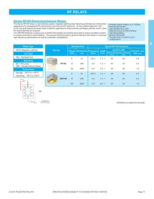
Series RF180 Electromechanical <strong>Relays</strong><br />
The Series RF180 relay is a hermetically sealed, magnetic-latching relay featuring extremely low intercontact<br />
capacitance for exceptional RF performance over the full UHF spectrum. Its low profi le height and .100”<br />
(2.54 mm) grid spaced terminals make it ideal for applications where extreme packaging density and/or close<br />
PC board spacing are required.<br />
The GRF180 features a unique ground shield that isolates and shields each lead to ensure excellent contactto-contact<br />
and pole-to-pole isolation. This ground shield provides a ground interface that results in improved<br />
high-frequency performance as well as parametric repeatability.<br />
• Excellent Signal integrity up to 10Gbps<br />
• Hermetically Sealed<br />
• High Resistance to ESD<br />
• Metal Enclosure for EMI shielding<br />
• High Repeatability<br />
• Broader bandwidth<br />
• Through-hole or surface-mount<br />
confi gurations<br />
Relay Type<br />
Nominal Coil<br />
Typical RF Performance<br />
RF<br />
DPDT Magnetic-Latching<br />
Coil Type<br />
180 = Standard Coil<br />
Mounting<br />
RF = Thru-hole<br />
GRF = Surface-Mount (Stub)<br />
Temperature<br />
Part No.<br />
RF180<br />
Voltage<br />
(Vdc)<br />
Resistance<br />
(Ω)<br />
Frequency<br />
(GHz)<br />
VSWR<br />
(max)<br />
Pole to Pole<br />
(min)<br />
Isolation (dB)<br />
Across Contacts<br />
(min)<br />
Insertion Loss<br />
(dB) (max)<br />
5 61 DC-2 1.3 : 1 50 30 0.2<br />
12 500 2-4 1.3 : 1 45 30 0.3<br />
26 2000 4-6 2.0 : 1 30 25 1.5<br />
Storage: –65°C to +125°C<br />
Operating: –55°C to +85°C<br />
COIL B<br />
GRF180<br />
5 61 DC-2 1.2 : 1 50 35 0.2<br />
12 500 2-4 1.3 : 1 35 30 0.4<br />
9<br />
10 –<br />
1<br />
26 2000 4-6 2.0 : 1 25 30 1.5<br />
8<br />
+<br />
7<br />
2<br />
3<br />
+<br />
180<br />
6<br />
5<br />
–<br />
4<br />
COIL A<br />
SCHEMATIC<br />
(Coil B Last Energized)<br />
Schematics as viewed from terminals<br />
© <strong>2013</strong> TELEDYNE RELAYS SPECIFICATIONS SUBJECT TO CHANGE WITHOUT NOTICE Page 11


