

2013 EMR Selection Guide.indd - Teledyne Relays
2013 EMR Selection Guide.indd - Teledyne Relays
2013 EMR Selection Guide.indd - Teledyne Relays

Create successful ePaper yourself
Turn your PDF publications into a flip-book with our unique Google optimized e-Paper software.
RF RELAYS<br />
RF<br />
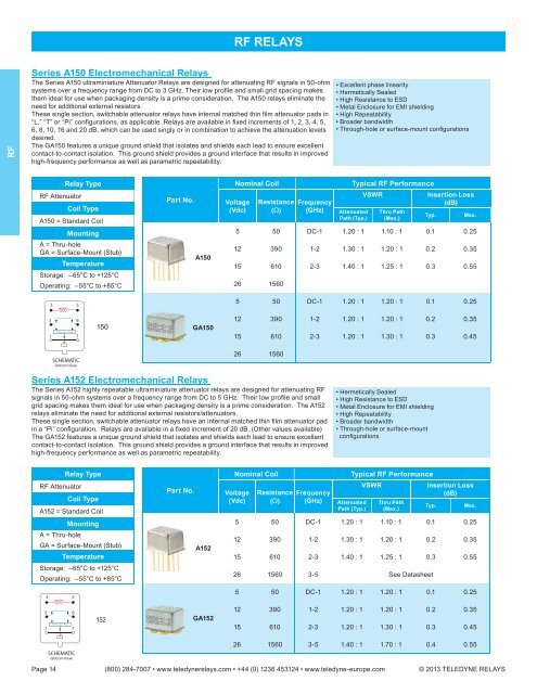
Series A150 Electromechanical <strong>Relays</strong><br />
The Series A150 ultraminiature Attenuator <strong>Relays</strong> are designed for attenuating RF signals in 50-ohm<br />
systems over a frequency range from DC to 3 GHz. Their low profi le and small grid spacing makes<br />
them ideal for use when packaging density is a prime consideration. The A150 relays eliminate the<br />
need for additional external resistors.<br />
These single section, switchable attenuator relays have internal matched thin fi lm attenuator pads in<br />
“L,” “T” or “Pi” confi gurations, as applicable. <strong>Relays</strong> are available in fi xed increments of 1, 2, 3, 4, 5,<br />
6, 8, 10, 16 and 20 dB, which can be used singly or in combination to achieve the attenuation levels<br />
desired.<br />
The GA150 features a unique ground shield that isolates and shields each lead to ensure excellent<br />
contact-to-contact isolation. This ground shield provides a ground interface that results in improved<br />
high-frequency performance as well as parametric repeatability.<br />
• Excellent phase linearity<br />
• Hermetically Sealed<br />
• High Resistance to ESD<br />
• Metal Enclosure for EMI shielding<br />
• High Repeatability<br />
• Broader bandwidth<br />
• Through-hole or surface-mount confi gurations<br />
RF Attenuator<br />
Relay Type<br />
Coil Type<br />
A150 = Standard Coil<br />
Mounting<br />
A = Thru-hole<br />
GA = Surface-Mount (Stub)<br />
Temperature<br />
Storage: –65°C to +125°C<br />
Operating: –55°C to +85°C<br />
3 5<br />
Part No.<br />
A150<br />
Nominal Coil<br />
Voltage<br />
(Vdc)<br />
Resistance<br />
(Ω)<br />
Frequency<br />
(GHz)<br />
Typical RF Performance<br />
Attenuated<br />
Path (Typ.)<br />
VSWR<br />
Thru Path<br />
(Max.)<br />
Insertion Loss<br />
(dB)<br />
Typ.<br />
Max.<br />
5 50 DC-1 1.20 : 1 1.10 : 1 0.1 0.25<br />
12 390 1-2 1.30 : 1 1.20 : 1 0.2 0.35<br />
15 610 2-3 1.40 : 1 1.25 : 1 0.3 0.55<br />
26 1560<br />
5 50 DC-1 1.20 : 1 1.20 : 1 0.1 0.25<br />
2<br />
1<br />
Attenuator Pad<br />
6<br />
7<br />
150<br />
GA150<br />
12 390 1-2 1.20 : 1 1.20 : 1 0.2 0.35<br />
15 610 2-3 1.20 : 1 1.30 : 1 0.3 0.45<br />
SCHEMATIC<br />
(Bottom View)<br />
26 1560<br />
Series A152 Electromechanical <strong>Relays</strong><br />
The Series A152 highly repeatable ultraminiature attenuator relays are designed for attenuating RF<br />
signals in 50-ohm systems over a frequency range from DC to 5 GHz. Their low profi le and small<br />
grid spacing makes them ideal for use when packaging density is a prime consideration. The A152<br />
relays eliminate the need for additional external resistors/attenuators.<br />
These single section, switchable attenuator relays have an internal matched thin fi lm attenuator pad<br />
in a “Pi” confi guration. <strong>Relays</strong> are available in a fi xed increment of 20 dB. (Other values available)<br />
The GA152 features a unique ground shield that isolates and shields each lead to ensure excellent<br />
contact-to-contact isolation. This ground shield provides a ground interface that results in improved<br />
high-frequency performance as well as parametric repeatability.<br />
• Hermetically Sealed<br />
• High Resistance to ESD<br />
• Metal Enclosure for EMI shielding<br />
• High Repeatability<br />
• Broader bandwidth<br />
• Through-hole or surface-mount<br />
confi gurations<br />
Relay Type<br />
RF Attenuator<br />
Coil Type<br />
A152 = Standard Coil<br />
Mounting<br />
A = Thru-hole<br />
GA = Surface-Mount (Stub)<br />
Temperature<br />
Storage: –65°C to +125°C<br />
Operating: –55°C to +85°C<br />
3 5<br />
Part No.<br />
A152<br />
Nominal Coil<br />
Voltage<br />
(Vdc)<br />
Resistance<br />
(Ω)<br />
Frequency<br />
(GHz)<br />
Typical RF Performance<br />
Attenuated<br />
Path (Typ.)<br />
VSWR<br />
Thru Path<br />
(Max.)<br />
Insertion Loss<br />
(dB)<br />
Typ.<br />
Max.<br />
5 50 DC-1 1.20 : 1 1.10 : 1 0.1 0.25<br />
12 390 1-2 1.30 : 1 1.20 : 1 0.2 0.35<br />
15 610 2-3 1.40 : 1 1.25 : 1 0.3 0.55<br />
26 1560 3-5 See Datasheet<br />
5 50 DC-1 1.20 : 1 1.20 : 1 0.1 0.25<br />
2<br />
1<br />
Attenuator Pad<br />
6<br />
7<br />
152<br />
GA152<br />
12 390 1-2 1.20 : 1 1.20 : 1 0.2 0.35<br />
15 610 2-3 1.20 : 1 1.30 : 1 0.3 0.45<br />
SCHEMATIC<br />
(Bottom View)<br />
26 1560 3-5 1.40 : 1 1.70 : 1 0.4 0.55<br />
Page 14 (800) 284-7007 • www.teledynerelays.com • +44 (0) 1236 453124 • www.teledyne-europe.com © <strong>2013</strong> TELEDYNE RELAYS


