

2013 EMR Selection Guide.indd - Teledyne Relays
2013 EMR Selection Guide.indd - Teledyne Relays
2013 EMR Selection Guide.indd - Teledyne Relays

Create successful ePaper yourself
Turn your PDF publications into a flip-book with our unique Google optimized e-Paper software.
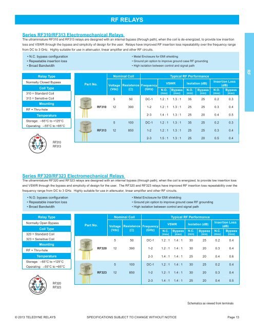
RF RELAYS<br />
Series RF310/RF313 Electromechanical <strong>Relays</strong><br />
The ultraminiature RF310 and RF313 relays are designed with an internal bypass (through path), when the coil is de-energized, to provide low insertion<br />
loss and VSWR through the bypass and simplicity of design for the user. <strong>Relays</strong> have improved RF insertion loss repeatability over the frequency range<br />
from DC to 3 GHz. Highly suitable for use in attenuator, linear amplifi er and other RF circuits.<br />
• N.C. bypass confi guration<br />
• Repeatable insertion loss<br />
• Broad Bandwidth<br />
• Metal Enclosure for EMI shielding<br />
• Ground pin option to improve ground case RF grounding<br />
• High isolation between control and signal path<br />
Relay Type<br />
Nominal Coil<br />
Typical RF Performance<br />
RF<br />
Normally Closed Bypass<br />
Coil Type<br />
310 = Standard Coil<br />
Part No.<br />
Voltage<br />
(Vdc)<br />
Resistance<br />
(Ω)<br />
Frequency<br />
(GHz)<br />
N.O.<br />
(max)<br />
VSWR<br />
Bypass<br />
(max)<br />
Isolation (dB)<br />
N.O.<br />
(min)<br />
Bypass<br />
(min)<br />
Insertion Loss<br />
(dB)<br />
N.O.<br />
(max)<br />
Bypass<br />
(max)<br />
313 = Sensitive Coil<br />
Mounting<br />
RF = Thru-hole<br />
RF310<br />
5 50 DC-1 1.2 : 1 1.3 : 1 35 25 0.2 0.3<br />
12 390 1-2 1.2 : 1 1.3 : 1 25 25 0.3 0.4<br />
Temperature<br />
2-3 1.4 : 1 1.3 : 1 25 20 0.4 0.5<br />
Storage: –65°C to +125°C<br />
Operating: –55°C to +85°C<br />
RF313<br />
5 100 DC-1 1.2 : 1 1.3 : 1 35 25 0.2 0.3<br />
12 850 1-2 1.2 : 1 1.3 : 1 25 25 0.3 0.4<br />
9<br />
8<br />
7<br />
1<br />
2<br />
3<br />
RF310<br />
RF313<br />
2-3 1.5 : 1 1.3 : 1 25 20 0.5 0.4<br />
Series RF320/RF323 Electromechanical <strong>Relays</strong><br />
The ultraminiature RF320 and RF323 relays are designed with an internal bypass (through path), when the coil is energized, to provide low insertion loss<br />
and VSWR through the bypass and simplicity of design for the user. The RF320 and RF323 relays have improved RF insertion loss repeatability over the<br />
frequency range from DC to 3 GHz. Highly suitable for use in attenuator, linear amplifi er and other RF circuits.<br />
• N.O. bypass confi guration<br />
• Repeatable insertion loss<br />
• Broad Bandwidth<br />
• Metal Enclosure for EMI shielding<br />
• Ground pin option to improve ground case RF grounding<br />
• High isolation between control and signal path<br />
Relay Type<br />
Normally Open Bypass<br />
Coil Type<br />
320 = Standard Coil<br />
323 = Sensitive Coil<br />
Mounting<br />
RF = Thru-hole<br />
Temperature<br />
Storage: –65°C to +125°C<br />
Operating: –55°C to +85°C<br />
Part No.<br />
RF320<br />
RF323<br />
Nominal Coil<br />
Voltage<br />
(Vdc)<br />
Resistance<br />
(Ω)<br />
Frequency<br />
(GHz)<br />
N.C.<br />
(max)<br />
Typical RF Performance<br />
VSWR<br />
Bypass<br />
(max)<br />
Isolation (dB)<br />
N.C.<br />
(min)<br />
Bypass<br />
(min)<br />
Insertion Loss<br />
(dB)<br />
N.C.<br />
(max)<br />
Bypass<br />
(max)<br />
5 50 DC-1 1.2 : 1 1.4 : 1 30 25 0.2 0.4<br />
12 390 1-2 1.2 : 1 1.4 : 1 30 20 0.3 0.4<br />
2-3 1.4 : 1 1.4 : 1 25 20 0.4 0.6<br />
5 100 DC-1 1.2 : 1 1.4 : 1 30 25 0.2 0.4<br />
12 850 1-2 1.2 : 1 1.4 : 1 30 20 0.3 0.4<br />
9<br />
8<br />
1<br />
2<br />
RF320<br />
RF323<br />
2-3 1.4 : 1 1.4 : 1 25 20 0.4 0.5<br />
6<br />
4<br />
Schematics as viewed from terminals<br />
© <strong>2013</strong> TELEDYNE RELAYS SPECIFICATIONS SUBJECT TO CHANGE WITHOUT NOTICE Page 13


