

2013 EMR Selection Guide.indd - Teledyne Relays
2013 EMR Selection Guide.indd - Teledyne Relays
2013 EMR Selection Guide.indd - Teledyne Relays

You also want an ePaper? Increase the reach of your titles
YUMPU automatically turns print PDFs into web optimized ePapers that Google loves.
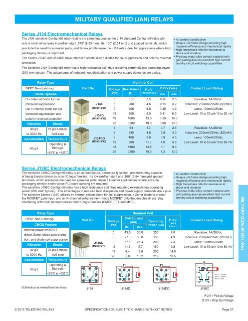
MILITARY QUALIFIED (JAN) RELAYS<br />
Series J134 Electromechanical <strong>Relays</strong><br />
The J134 sensitive Centigrid® relay retains the same features as the J114 standard Centigrid® relay with<br />
only a minimal increase in profi le height .375” (9.53 mm). Its .100” (2.54 mm) grid spaced terminals, which<br />
preclude the need for spreader pads, and its low profi le make the J134 relay ideal for applications where high<br />
packaging density is important.<br />
The Series J134D and J134DD have internal discrete silicon diodes for coil suppression and polarity reversal<br />
protection.<br />
The sensitive J134 Centigrid® relay has a high resistance coil, thus requiring extremely low operating power<br />
(200 mw typical). The advantages of reduced heat dissipation and power supply demands are a plus.<br />
• All welded construction<br />
• Unique uni-frame design providing high<br />
magnetic effi ciency and mechanical rigidity<br />
• High force/mass ratio for resistance to<br />
shock and vibration<br />
• Precious metal alloy contact material with<br />
gold plating assures excellent high current<br />
and dry circuit switching capabilities<br />
Relay Type<br />
DPDT Non-Latching<br />
Diode Options<br />
D = Internal diode for coil<br />
transient suppression<br />
DD = Internal diode for coil<br />
transient suppression and<br />
polarity reversal protection<br />
Vibration Shock<br />
30 g’s 75 g’s 6 msec,<br />
to 3000 Hz half-sine<br />
Acceleration Temperature<br />
Operating &<br />
50 g’s Storage:<br />
–65°C to +125°C<br />
Part No.<br />
J134<br />
(M39016/41)<br />
J134D<br />
(M39016/42)<br />
J134DD<br />
(M39016/43)<br />
Voltage<br />
(Vdc)<br />
Resistance<br />
(Ω)<br />
Nominal Coil<br />
P.U.V<br />
(Vdc) (max.)<br />
D.O.V (Vdc)<br />
min.<br />
max.<br />
Contact Load Rating<br />
5 100 3.5 0.12 2.5 Resistive: 1A/28Vdc<br />
6 200 4.5 0.18 3.2 Inductive: 200mA/28Vdc (320mH)<br />
9 400 6.8 0.35 4.9 Lamp: 100mA/28Vdc<br />
12 800 9.0 0.41 6.5 Low Level: 10 to 50 uA/10 to 50 mV<br />
18 1600 13.5 0.59 10.0<br />
26 3200 18.0 0.89 13.0<br />
5 64 3.7 0.7 2.6 Resistive: 1A/28Vdc<br />
6 125 4.8 0.8 3.0 Inductive: 200mA/28Vdc (320mH)<br />
9 400 8.0 0.9 4.5 Lamp: 100mA/28Vdc<br />
12 800 11.0 1.0 5.8 Low Level: 10 to 50 uA/10 to 50 mV<br />
18 1600 14.5 1.1 9.0<br />
26 3200 19.0 1.3 13.0<br />
Series J136C Electromechanical <strong>Relays</strong><br />
The sensitive J136C Centigrid® relay is an ultraminiature, hermetically sealed, armature relay capable<br />
of being directly driven by most IC logic families. Its low profi le height and .100” (2.54 mm) grid spaced<br />
terminals, which precludes the need for spreader pads, make it ideal for applications where extreme<br />
packaging density and/or close PC board spacing are required.<br />
The sensitive J136C Centigrid® relay has a high resistance coil, thus requiring extremely low operating<br />
power (200 mW, typical). The advantages of reduced heat dissipation and power supply demands are a plus.<br />
The sensitive Series J136C utilizes an internal silicon diode for coil suppression, a Zener diode to protect<br />
the MOSFET gate input, and an N-channel enhancement-mode MOSFET chip that enables direct relay<br />
interfacing with most microprocessor and IC logic families (CMOS, TTL and MOS).<br />
Relay Type<br />
DPDT Non-Latching<br />
CMOS Feature<br />
Internal power MOSFET<br />
driver, Zener diode gate protection,<br />
and diode coil suppression<br />
Vibration Shock<br />
30 g’s 75 g’s 6 msec,<br />
to 3000 Hz half-sine<br />
Acceleration Temperature<br />
Operating &<br />
50 g’s Storage:<br />
–65°C to +125°C<br />
Part No.<br />
7<br />
6<br />
5<br />
8<br />
4<br />
J136C<br />
(M28776/7)<br />
1<br />
2<br />
3<br />
Voltage<br />
(Vdc)<br />
Nominal Coil<br />
Coil Current<br />
(mA)<br />
Min.<br />
Max.<br />
Operating<br />
Power (m W )<br />
P.U.V<br />
(Vdc)<br />
(max.)<br />
• All welded construction<br />
• Unique uni-frame design providing high<br />
magnetic effi ciency and mechanical rigidity<br />
• High force/mass ratio for resistance to<br />
shock and vibration<br />
• Precious metal alloy contact material with<br />
gold plating assures excellent high current<br />
and dry circuit switching capabilities<br />
Contact Load Rating<br />
5 43.0 56.0 250 4.0 Resistive: 1A/28Vdc<br />
6 27.0 33.0 180 4.9 Inductive: 200mA/28Vdc (320mH)<br />
9 17.8 26.4 203 7.3 Lamp: 100mA/28Vdc<br />
12 11.3 17.7 180 9.8 Low Level: 10 to 50 uA/10 to 50 mV<br />
18 8.4 13.8 203 14.6<br />
26 5.8 10.2 219 19.5<br />
7<br />
8<br />
6 2<br />
5<br />
4<br />
1<br />
3<br />
7<br />
8<br />
6 2<br />
5<br />
4<br />
1<br />
3<br />
–<br />
9<br />
8<br />
7<br />
6<br />
10<br />
+ 1<br />
2<br />
3<br />
4<br />
PIN 1: + SUPPLY<br />
PIN 9: – SUPPLY<br />
PIN 10: GATE<br />
MILITARY QUALIFIED (JAN)<br />
Schematics as viewed from terminals<br />
J134 J134D J134DD J136C<br />
P.U.V = Pick-Up Voltage<br />
D.O.V = Drop-Out Voltage<br />
© <strong>2013</strong> TELEDYNE RELAYS SPECIFICATIONS SUBJECT TO CHANGE WITHOUT NOTICE Page 27


