

2013 EMR Selection Guide.indd - Teledyne Relays
2013 EMR Selection Guide.indd - Teledyne Relays
2013 EMR Selection Guide.indd - Teledyne Relays

Create successful ePaper yourself
Turn your PDF publications into a flip-book with our unique Google optimized e-Paper software.
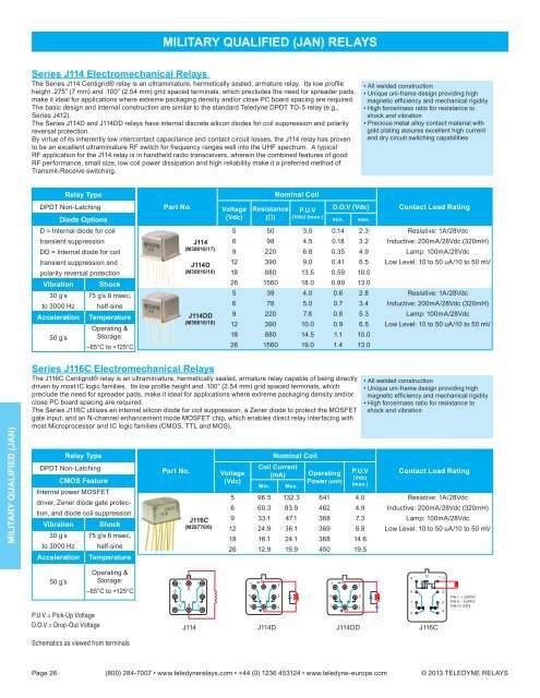
MILITARY QUALIFIED (JAN) RELAYS<br />
Series J114 Electromechanical <strong>Relays</strong><br />
The Series J114 Centigrid® relay is an ultraminiature, hermetically sealed, armature relay. Its low profi le<br />
height .275” (7 mm) and .100” (2.54 mm) grid spaced terminals, which precludes the need for spreader pads,<br />
make it ideal for applications where extreme packaging density and/or close PC board spacing are required.<br />
The basic design and internal construction are similar to the standard <strong>Teledyne</strong> DPDT TO-5 relay (e.g.,<br />
Series J412).<br />
The Series J114D and J114DD relays have internal discrete silicon diodes for coil suppression and polarity<br />
reversal protection.<br />
By virtue of its inherently low intercontact capacitance and contact circuit losses, the J114 relay has proven<br />
to be an excellent ultraminiature RF switch for frequency ranges well into the UHF spectrum. A typical<br />
RF application for the J114 relay is in handheld radio transceivers, wherein the combined features of good<br />
RF performance, small size, low coil power dissipation and high reliability make it a preferred method of<br />
Transmit-Receive switching.<br />
• All welded construction<br />
• Unique uni-frame design providing high<br />
magnetic effi ciency and mechanical rigidity<br />
• High force/mass ratio for resistance to<br />
shock and vibration<br />
• Precious metal alloy contact material with<br />
gold plating assures excellent high current<br />
and dry circuit switching capabilities<br />
Relay Type<br />
DPDT Non-Latching<br />
Diode Options<br />
D = Internal diode for coil<br />
transient suppression<br />
DD = Internal diode for coil<br />
transient suppression and<br />
polarity reversal protection<br />
Vibration Shock<br />
30 g’s 75 g’s 6 msec,<br />
to 3000 Hz half-sine<br />
Acceleration Temperature<br />
Operating &<br />
50 g’s Storage:<br />
–65°C to +125°C<br />
Part No.<br />
J114<br />
(M39016/17)<br />
J114D<br />
(M39016/18)<br />
J114DD<br />
(M39016/18)<br />
Voltage<br />
(Vdc)<br />
Resistance<br />
(Ω)<br />
Nominal Coil<br />
P.U.V<br />
(Vdc) (max.)<br />
D.O.V (Vdc)<br />
min.<br />
max.<br />
Contact Load Rating<br />
5 50 3.5 0.14 2.3 Resistive: 1A/28Vdc<br />
6 98 4.5 0.18 3.2 Inductive: 200mA/28Vdc (320mH)<br />
9 220 6.8 0.35 4.9 Lamp: 100mA/28Vdc<br />
12 390 9.0 0.41 6.5 Low Level: 10 to 50 uA/10 to 50 mV<br />
18 880 13.5 0.59 10.0<br />
26 1560 18.0 0.89 13.0<br />
5 39 4.0 0.6 2.8 Resistive: 1A/28Vdc<br />
6 78 5.0 0.7 3.4 Inductive: 200mA/28Vdc (320mH)<br />
9 220 7.8 0.8 5.3 Lamp: 100mA/28Vdc<br />
12 390 10.0 0.9 6.5 Low Level: 10 to 50 uA/10 to 50 mV<br />
18 880 14.5 1.1 10.0<br />
26 1560 19.0 1.4 13.0<br />
MILITARY QUALIFIED (JAN)<br />
Series J116C Electromechanical <strong>Relays</strong><br />
The J116C Centigrid® relay is an ultraminiature, hermetically sealed, armature relay capable of being directly<br />
driven by most IC logic families. Its low profi le height and .100” (2.54 mm) grid spaced terminals, which<br />
preclude the need for spreader pads, make it ideal for applications where extreme packaging density and/or<br />
close PC board spacing are required.<br />
The Series J116C utilizes an internal silicon diode for coil suppression, a Zener diode to protect the MOSFET<br />
gate input, and an N-channel enhancement mode MOSFET chip, which enables direct relay interfacing with<br />
most Microprocessor and IC logic families (CMOS, TTL and MOS).<br />
Relay Type<br />
DPDT Non-Latching<br />
CMOS Feature<br />
Internal power MOSFET<br />
driver, Zener diode gate protection,<br />
and diode coil suppression<br />
Vibration Shock<br />
30 g’s 75 g’s 6 msec,<br />
to 3000 Hz half-sine<br />
Acceleration Temperature<br />
Part No.<br />
J116C<br />
(M28776/6)<br />
Voltage<br />
(Vdc)<br />
Nominal Coil<br />
Coil Current<br />
(mA)<br />
Min.<br />
Max.<br />
Operating<br />
Power (mW)<br />
P.U.V<br />
(Vdc)<br />
(max.)<br />
• All welded construction<br />
• Unique uni-frame design providing high<br />
magnetic effi ciency and mechanical rigidity<br />
• High force/mass ratio for resistance to<br />
shock and vibration<br />
Contact Load Rating<br />
5 96.5 132.3 641 4.0 Resistive: 1A/28Vdc<br />
6 60.3 83.9 462 4.9 Inductive: 200mA/28Vdc (320mH)<br />
9 33.1 47.1 368 7.3 Lamp: 100mA/28Vdc<br />
12 24.9 36.1 369 9.8 Low Level: 10 to 50 uA/10 to 50 mV<br />
18 16.1 24.1 368 14.6<br />
26 12.9 19.9 450 19.5<br />
50 g’s<br />
P.U.V = Pick-Up Voltage<br />
D.O.V = Drop-Out Voltage<br />
Operating &<br />
Storage:<br />
–65°C to +125°C<br />
Schematics as viewed from terminals<br />
7<br />
8<br />
6<br />
5 4<br />
1<br />
2<br />
3<br />
–<br />
9<br />
10 + 1<br />
7<br />
8<br />
1<br />
7<br />
8<br />
1<br />
8<br />
2<br />
6 2<br />
6 2<br />
7<br />
3<br />
5<br />
4<br />
3<br />
5<br />
4<br />
3<br />
6<br />
4<br />
J114 J114D J114DD J116C<br />
PIN 1: + SUPPLY<br />
PIN 9: – SUPPLY<br />
PIN 10: GATE<br />
Page 26 (800) 284-7007 • www.teledynerelays.com • +44 (0) 1236 453124 • www.teledyne-europe.com © <strong>2013</strong> TELEDYNE RELAYS


