6 - Kuwait Oil Company
6 - Kuwait Oil Company
6 - Kuwait Oil Company

Create successful ePaper yourself
Turn your PDF publications into a flip-book with our unique Google optimized e-Paper software.
The second screen of ALES (Figure 6) is meant for<br />
entering reservoir & fluid parameters and to perform<br />
the Nodal Analysis. The system, shows warning<br />
messages when the well can flow naturally what is<br />
required to produce and when the desired production<br />
rate is greater than the absolute open flow. In this<br />
way the user can check the physical consistency or<br />
integrity of the data by matching the production<br />
(if any) with the production history in this well or<br />
neighbor wells and/or the operational conditions in<br />
the artificial lift methods existing in the field. This is<br />
a very important step since ALES rules are based on<br />
calculations rather than rules of thumb, meaning that<br />
inconsistent data will change the evaluation results.<br />
Figure 6. Second screen view of ALES. Data<br />
Entry, PI calculation and Nodal Analysis<br />
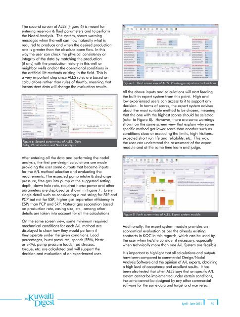
Figure 7. Third screen view of ALES. Pre-design outputs and calculations<br />
All the above inputs and calculations will start feeding<br />
the built-in expert system from this point. High and<br />
low experienced users can access to it to support any<br />
decision. In terms of scores, the expert system advises<br />
about the most suitable method to be chosen, meaning<br />
that the one with the highest scores should be selected<br />
(refer to Figure 8). However, there are some warnings<br />
shown on the same screen view that explain why some<br />
specific method got lower score than another such as<br />
conditions close or exceeding the limits, high frictions,<br />
expected short run life and reliability, etc. This way,<br />
the user can understand the assessment of the expert<br />
module and at the same time learn and judge.<br />
After entering all the data and performing the nodal<br />
analysis, the first pre-design calculations are made<br />
providing the user some outputs that become inputs<br />
for the A/L method selection and evaluating the<br />
requirements. The expected pump intake & discharge<br />
pressure, free gas into pump at the suggested setting<br />
depth, down hole rate, required horse power and other<br />
parameters are displayed as shown in Figure 7. Every<br />
single detail such as considering a rod string for SRP and<br />
PCP but not for ESP, higher gas separation efficiency in<br />
ESPs than PCP and SRP, Natural gas separation based<br />
on production rate, casing size, etc., among other<br />
details are taken into account for all the calculations<br />
On the same screen view, some minimum required<br />
mechanical conditions for each A/L method are<br />
displayed to show how they would perform if<br />
they operate under the given conditions. Load<br />
percentages, burst pressures, speeds (RPM, Hertz<br />
or SPM), pump pressure loads, rod stresses,<br />
torque, etc. are calculated and will support the<br />
decision and evaluation of an experienced user.<br />
Figure 8. Forth screen view of ALES. Expert system module<br />
Additionally, the expert system module provides an<br />
economical evaluation as per the already existing<br />
contracts in KOC in this regards, which can be used by<br />
the user when he/she consider it necessary, especially<br />
when technically more than one A/L System are feasible.<br />
It is important to highlight that all calculations and outputs<br />
have been compared to commercial Design/Nodal<br />
Analysis Software and the opinion of A/L experts, obtaining<br />
a high level of acceptance and excellent results. It has<br />
been also tested that when ALES says that an specific A/L<br />
system cannot be implemented under certain conditions,<br />
the same cannot be designed by any other commercial<br />
software for the same data and target and vice versa.<br />
April - June 2013 35