Create successful ePaper yourself
Turn your PDF publications into a flip-book with our unique Google optimized e-Paper software.
English<br />
Ref. No. 28-8933-0801-04/1232<br />
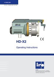
<strong>Star</strong> <strong>G2</strong><br />
Operating Instructions<br />
<strong>IRO</strong> <strong>AB</strong><br />
Box 54 SE-523 22 Ulricehamn SWEDEN<br />
Tel: (+46) 321 297 00 Fax: (+46) 321 298 00<br />
info@iro.se www.iroab.com
Contents<br />
<strong>Star</strong> <strong>G2</strong> 1<br />
Contents................................................................................................... 1<br />
Technical Specifications........................................................................... 2<br />
Main Parts................................................................................................ 3<br />
Operating Diagram................................................................................... 4<br />
Installation................................................................................................ 5<br />
Mains Connection.................................................................................. 6-8<br />
Wiring Diagram......................................................................................... 9<br />
Connections........................................................................................... 10<br />
Jumper/ Speed settings...........................................................................11<br />
Yarn Control............................................................................................ 12<br />
Yarn Control Recommendations............................................................. 13<br />
S/z Adjustment....................................................................................... 14<br />
Threading............................................................................................... 15<br />
Balloon Adjustment................................................................................. 16<br />
Cat Adjustment....................................................................................... 17<br />
Sensor Adjustment................................................................................. 18<br />
Maintenance........................................................................................... 19<br />
Fault Finding........................................................................................... 20<br />
Declaration of conformity........................................................................ 21<br />
This section contains important safety information. Read the manual carefully before installing, using or<br />
maintaining the feeder.<br />
WARNING<br />
Indicates a possible dangerous situation which<br />
could result in serious injury or damage to the unit.<br />
CAUTION<br />
Indicates a possible dangerous situation which<br />
could result in minor/moderate injury or damage<br />
to the unit.<br />
NOTE<br />
Used in order to draw attention to important information,<br />
which facilitates operation or handling.<br />
Ref. No. 28-8933-0801-04/1232<br />
ORIGINAL LANGUAGE INSTRUCTION<br />
Iro ab reserve the right to change the contents of the user’s guide<br />
and technical specifications without prior notification.
Technical specifications<br />
<strong>Star</strong> <strong>G2</strong> 2<br />
WARNING!<br />
• The power supply must be switched off at the mains<br />
before any work is carried out on the feeder, the<br />
transformer or any other electrical components. The<br />
feeder and the transformer cabinet must be fully assembled<br />
before the power supply is connected.<br />
• The weft feeder ON/OFF-switch does not cut off the<br />
main power supply. Turn off the main switch before<br />
any work is carried out on the electrical circuit.<br />
• The feeder and transformer contain electrical components<br />
that retain an electric current up to three<br />
minutes after disconnection<br />
• All work on electrical components must be carried<br />
out by a qualified electrician.<br />
• This product is not intended for use in potentially<br />
explosive atmospheres or in zones classified according<br />
to the european directive 94/9/ec. Please contact<br />
iro ab if products for use in a potentially explosive<br />
atmosphere are required.<br />
• Always turn off the main switch or isolate the<br />
power supply and disconnect the air supply before<br />
connecting or disconnecting the feeder, the control<br />
board or any of the circuit boards<br />
WARNING!<br />
• Routine checks for damaged or worn parts must be<br />
made before operating this equipment. Any part that<br />
is worn or damaged should be properly repaired or<br />
replaced by authorized personnel. To avoid risk of<br />
injury DO NOT operate this equipment if any component<br />
does not appear to be functioning correctly.<br />
CAUTION!<br />
• Caution must be taken in the close vicinity of the<br />
feeder as it contains moving parts that can cause<br />
injuries and, in normal operation, starts without prior<br />
warning.<br />
• To comply with c.E. Regulations only replacement<br />
parts approved by <strong>IRO</strong> <strong>AB</strong> may be used.<br />
• The feeder is an industrial product and therefore not<br />
approved to use household environments /in residential<br />
areas.<br />
NOTE<br />
• To ensure the selection of the most suitable feeder and associated accessories, it is recommended making<br />
weaving tests with the intended yarns.<br />
• Please dispose of obsolete or unwanted equipment responsibly, taking into consideration any local regulations<br />
regarding the disposal and / or recycling of materials that are applicable<br />
Technical specifications<br />
Max 1200 m/min<br />
76 dB (A)<br />
4.7 kg<br />
Max 5 mm<br />
Min 5° C-Max 40° C<br />
5,5 - 7 bar<br />
Max 85 %<br />
Max 2,2 mm<br />
Ref. No. 28-8933-0801-04/1232<br />
200 - 575V 400VA<br />
3,3 kg<br />
Power Supply<br />
Note<br />
Max T 10A<br />
Fuse<br />
Subject to technical modifications.
Main parts<br />
<strong>Star</strong> <strong>G2</strong> 3<br />
Yarn break detector<br />
Yarn store sensors<br />
Winding disc<br />
Brush ring holder<br />
adjustment<br />
Mount<br />
Spool body<br />
S/Z Switch<br />
ON/OFF Switch<br />
Indicator<br />
Max speed<br />
(Mech. sensor only)<br />
CAT<br />
Adjustment<br />
Ref. No. 28-8933-0801-04/1232
Operating diagram<br />
<strong>Star</strong> <strong>G2</strong> 4<br />
Motor<br />
13,8 Ω +/- 5%<br />
TB2<br />
Motor control unit<br />
S/Z<br />
TB1<br />
ON/OFF<br />
P3 – P10<br />
+<br />
+<br />
P2<br />
Machine stop signal<br />
Fuse panel<br />
P1 P1 P1<br />
Transformer<br />
Ref. No. 28-8933-0801-04/1232<br />
Mains supply
Installation<br />
<strong>Star</strong> <strong>G2</strong> 5<br />
NOTE<br />
Condensation can form on the weft feeder when it is moved from the cold environment of the warehouse<br />
to the warmer environment of the loom room. Make sure that the feeder is dry before switching it on.<br />
CAution!<br />
The unit should not be mounted directly on the<br />
weaving machine.<br />
Use a separate floor stand.<br />
Note<br />
Feeders’ stand and creel must be connected to the<br />
earth of the loom.<br />
Note<br />
Place the creel behind the feeder’s stand avoiding<br />
sharp angles to the yarn path from the creel output<br />
to the feeders.<br />
Feeders with Mechanical sensors must be mounted<br />
within 45° of the horizontal plane.<br />
*Max 15° with low sensor spring force.<br />
45°<br />
45°<br />
45°<br />
45°<br />
Ensure that the mount screws are correctly<br />
tightened.<br />
Ref. No. 28-8933-0801-04/1232
Mains connection<br />
<strong>Star</strong> <strong>G2</strong> 6<br />
warning<br />
Turn off the main switch before any work is carried out on the electrical circuit.<br />
The power supply to the feeder must not be<br />
disrupted when the weaving machine stops.<br />
Mains supply<br />
Main switch<br />
Emergency stop<br />
The phase sequence does not effect the direction<br />
of rotation.<br />
L1 L2 L3<br />
Ref. No. 28-8933-0801-04/1232<br />
Z<br />
S
Mains connection<br />
<strong>Star</strong> <strong>G2</strong> 7<br />
Variations in main voltage.<br />
Nominal Voltage Frequence<br />
200 - 220 V 190 - 230 V 50/ 60 Hz<br />
260 V 235 - 285 V 50/ 60 Hz<br />
346 V 310 - 380 V 50/ 60 Hz<br />
380 V 340 - 420 V 50/ 60 Hz<br />
400/ 415 V 365 - 445 V 50/ 60 Hz<br />
440/460 V 405 - 495 V 50/ 60 Hz<br />
480/ 500 V 440 - 540 V 50/ 60 Hz<br />
550/ 575/ 600 V 520 - 630 V 50/ 60 Hz<br />
Check the wiring diagram before any<br />
connections are carried out.<br />
With main switch<br />
Without main switch<br />
Ref. No. 28-8933-0801-04/1232
Mains connection<br />
<strong>Star</strong> <strong>G2</strong> 8<br />
The wiring diagrams on the following page refer to control boxes equipped with a main switch<br />
(as in fig.1 below). The mains supply shall be connected to L1, L2, L3 and EARTH. When the control<br />
box is not equipped with a main switch the mains supply shall be connected as in fig.2.<br />
With main switch<br />
Fig 1<br />
Without main switch<br />
Fig 2<br />
Ref. No. 28-8933-0801-04/1232
Wiring diagram<br />
<strong>Star</strong> <strong>G2</strong> 9<br />
200V/ 220V - 346V - 380V - 400V/ 415V<br />
200V / 220V<br />
346V<br />
380V<br />
400V / 415V<br />
L1<br />
L2<br />
L3<br />
135 V Green P1/1<br />
PRIM<br />
R<br />
SEC<br />
10/9.5 V White P1/4<br />
Mains supply<br />
135 V Green P1/2<br />
PRIM<br />
PRIM<br />
S<br />
T<br />
SEC<br />
SEC<br />
10/9.5 V White P1/5<br />
135V Green P1/3<br />
10/9.5 V White P1/6<br />
L1 L2 L3<br />
1<br />
3<br />
5<br />
2<br />
4<br />
6<br />
PE<br />
440V/ 460V - 480V/ 500V - 550V/ 575V/ 600V<br />
440V / 460V<br />
480V / 500V<br />
550V / 575V / 600V<br />
L1<br />
L2<br />
L3<br />
135 V Green P1/1<br />
PRIM<br />
R<br />
SEC<br />
10/9,5 V White P1/4<br />
Mains supply<br />
135 V Green P1/2<br />
PRIM<br />
PRIM<br />
S<br />
T<br />
SEC<br />
SEC<br />
10/9,5 V White P1/5<br />
135 V Green P1/3<br />
10/9,5 V White P1/6<br />
L1 L2 L3<br />
1<br />
3<br />
5<br />
2<br />
4<br />
6<br />
PE<br />
Ref. No. 28-8933-0801-04/1232
Connections<br />
<strong>Star</strong> <strong>G2</strong> 10<br />
Control box 4129 fuse panel<br />
2 and 4 colour 8 colour<br />
C1 C2 C3<br />
T2A<br />
S7 S8 S9 S10 S11 S12 S13 S14<br />
T2A<br />
T2A<br />
S5<br />
S6<br />
T2A<br />
T2A<br />
T2A<br />
S4<br />
T2A<br />
Machine stop<br />
Stop indicator<br />
Common/<br />
3<br />
Common/<br />
5<br />
Normally closed<br />
2<br />
Normally closed<br />
6<br />
Normally open<br />
1<br />
Normally open<br />
4<br />
Control box 4729 fuse panel<br />
4 and 8 colour<br />
P12<br />
1<br />
1<br />
P11<br />
P2<br />
3 2 1<br />
S14<br />
S13<br />
S12 S11 S10 S9 S8<br />
S7<br />
C1<br />
S3<br />
P1<br />
S2 S1 S6 S5 S4<br />
C3<br />
C2<br />
1 2 3 4 5 6 7<br />
Signal to weaving machine a Opto coupler, low Opto coupler, high<br />
8 Colour<br />
4 Colour/<br />
P2<br />
3 2 1<br />
P2<br />
3 2 1<br />
Ref. No. 28-8933-0801-04/1232<br />
P12 1 P11<br />
8 6 4 2<br />
7 5 3 1<br />
1<br />
Earth / Erde<br />
Max. 24V
Jumper/ speed settings<br />
<strong>Star</strong> <strong>G2</strong> 11<br />
Motor circuit board jumpers<br />
The feeder is equipped with jumpers on the motor circuit board that adapt the feeders operation to the<br />
characteristics of the weaving process. (Weaving machine settings have priority over jumper settings).<br />
J1<br />
J2<br />
J1<br />
Yarn break sensor filtering - RIGID YARNS<br />
J1<br />
Yarn break sensor filtering- NORMAL<br />
J2<br />
Stand-by mode - EN<strong>AB</strong>LE<br />
J2<br />
Stand-by mode DIS<strong>AB</strong>LE<br />
Maximum speed<br />
To set the maximum speed rotate the disc to the appropriate<br />
position.<br />
Ref. No. 28-8933-0801-04/1232<br />
1 = 1200 m/min<br />
2 = 960 m/min<br />
3 = 630 m/min<br />
4 = 400 m/min<br />
1<br />
2 3<br />
4
Yarn control<br />
<strong>Star</strong> <strong>G2</strong> 12<br />
When weaving certain types of yarn and under special weaving conditions it may be necessary to use yarn control<br />
elements in positions 1 and 3. The tables below and on the following page describe suitable combinations.<br />
Yarn control element positions<br />
2<br />
3<br />
1<br />
Yarn control element – type and position<br />
ELEMENT TYPE Position ELEMENT TYPE Position<br />
A<br />
1<br />
F<br />
B<br />
1<br />
3<br />
G<br />
C<br />
1<br />
H<br />
Brush<br />
2<br />
D<br />
1<br />
J<br />
(CAT)<br />
3<br />
Ref. No. 28-8933-0801-04/1232<br />
E<br />
K<br />
3
Yarn control recommendations<br />
<strong>Star</strong> <strong>G2</strong> 13<br />
Yarn Rapier Projectile<br />
YARN COUNT TENSIONERS YARN COUNT TENSIONERS<br />
1 2 3<br />
1 2<br />
Spun cotton and<br />
covered elastic<br />
Ne 74 - 35 A H/ I J/ I+K<br />
Ne 59 - 9 A H/ II J/ II+K<br />
Ne 15 - 4 A H/ III J/ III+K<br />
Ne 6 - 1,2 D H/ IIII B+B+K<br />
Ne > 35 A H/ I<br />
Ne 59 - 16 A H/ II<br />
Ne 20 - 4 A H/ III<br />
Ne 6 - 1,2 D H/ IIII<br />
Wool<br />
Nm 120 - 60 A H/ I B+B+K<br />
Nm 100 - 14 A H/ II B+B+K<br />
Nm 25 - 7 A H/ III B+B+K<br />
Nm 10 - 2 D H/ IIII B+B+K<br />
Nm > 60 A H/ I<br />
Nm 100 - 27 A H/ II<br />
Nm 33 - 7 A H/ III<br />
Nm 10 - 2 D H/ IIII<br />
Stiff yarns, Jute<br />
and Flax (linen)<br />
Nm 120 - 30 A H/ II B+B+K<br />
Nm 35 - 20 A H/ III B+B+K<br />
Nm 26 - 7 A H/ III B+B+K<br />
Nm 10 - 2 D H/ IIII K<br />
Nm 120 - 27 A H/ II<br />
Nm 33 - 7 D H/ III<br />
Nm 10 - 2 D H/ IIII<br />
Chenille<br />
Nm 120 - 20 A H/ II J/ II+K<br />
Nm 25 - 7 A H/ III K<br />
Nm 10 - 2 D H/ IIII B+B+K<br />
Nm 120 - 50 A H/ I<br />
Nm 67 - 7 A H/ II<br />
Nm 10 - 2 D H/ III<br />
Fancy yarns,<br />
Slub and Nub<br />
Nm 120 - 50 B H/ I B+B+K<br />
Nm 67 - 7 B H/ II B+B+K<br />
Nm 10 - 2 B H/ III B+B+K<br />
Nm 120 - 50 B H/ I<br />
Nm 67 - 7 B H/ II<br />
Nm 10 - 2 B H/ III<br />
High Twist<br />
Tex 4 - 20 C H/ I B+B+K<br />
Tex 15 - 50 C H/ II B+B+K<br />
Tex 40 - 100 C H/ III B+B+K<br />
Tex 4 - 20 C H/ I<br />
Tex 15 - 100 C H/ II<br />
Tex 80 - 400 C H/ III<br />
Endless Filament<br />
Tex 4 - 20 C H/ I J/ I+K<br />
Tex 15 - 40 C H/ II J/ II+K<br />
Tex 30 - 100 A H/ II J/ III+K<br />
Tex 80 - 400 A H/III B+B+K<br />
Tex 4 - 20 C H/ I<br />
Tex 15 - 100 C H/ II<br />
Tex 80 - 400 A H/ III<br />
Tension rating: I=soft, II=medium, III=stiff, IIII=extra stiff<br />
Ref. No. 28-8933-0801-04/1232<br />
NOTE<br />
As tensioner performance can be affected by various factors connected to the specific yarns being used<br />
the above recommendations are intended purely as a guide. In case of any uncertainty it is recommended that<br />
a weft insertion test be carried out.
S/Z adjustment<br />
<strong>Star</strong> <strong>G2</strong> 14<br />
Switch off the feeder.<br />
Grip the winding disc and, whilst pressing<br />
the orange button on the front of the spool<br />
body, rotate the disc until the button is felt to<br />
locate. Aligning the mark on the winding disc<br />
with the line on the motor house gives the<br />
zero separation position.<br />
To adjust, press in the button and revolve the<br />
winding disc in the appropriate direction.<br />
The separation increases from 0 to 2,2 mm<br />
the more the disc is rotated.<br />
The separation must be distinct, but not<br />
excessive.<br />
Ref. No. 28-8933-0801-04/1232<br />
Set the direction of rotation with the switch.<br />
(The feeder is deactivated in the standby<br />
position (0))<br />
0
Threading<br />
<strong>Star</strong> <strong>G2</strong> 15<br />
WITHOUT CAT<br />
• Switch off the feeder.<br />
• Align the winding disc eyelet (1).<br />
• Open the brush holder (see page 16).<br />
• Thread the needle all the way through the<br />
feeder and output eyelet.<br />
• Pull the yarn through.<br />
• Restart the feeder.<br />
1<br />
WITH CAT<br />
• Switch off the feeder.<br />
• Align the winding disc eyelet.<br />
• Thread the needle through the feeder and balloon<br />
control brush.<br />
• <strong>Star</strong>t the feeder and fill the yarn store.<br />
• Insert the threading needle into the CAT (2) as<br />
far as possible.<br />
• Pulling the yarn (3) will cause it to wrap around<br />
the threading needle.<br />
• When the threading needle is pulled out (4) the<br />
yarn will follow.<br />
2<br />
3<br />
4<br />
Ref. No. 28-8933-0801-04/1232
Balloon adjustment<br />
<strong>Star</strong> <strong>G2</strong> 16<br />
Adjust the balloon control.<br />
NOTE<br />
Excessive brush tension will cause abnormal wear.<br />
Remove the brush ring<br />
Press down the lip on the slide with a screwdriver.<br />
Pull off the brush ring.<br />
Replace the brush ring<br />
Press the brush ring on to the slide. The ’click’ ensures that<br />
the brush ring is properly positioned.<br />
Ref. No. 28-8933-0801-04/1232
CAT adjustment<br />
<strong>Star</strong> <strong>G2</strong> 17<br />
Control input yarn tension to the CAT.<br />
NOTE<br />
The brush ring shall only be used for<br />
balloon control.<br />
Adjustment of the output tension.<br />
Ref. No. 28-8933-0801-04/1232
Sensor adjustment<br />
<strong>Star</strong> <strong>G2</strong> 18<br />
The sensors are adjustable in three stages:<br />
Level 1 - Very fine yarns<br />
Level 2 - Normal setting<br />
Level 3 - Very heavy yarns<br />
Ref. No. 28-8933-0801-04/1232
Maintenance<br />
<strong>Star</strong> <strong>G2</strong> 19<br />
Cleaning<br />
It is recommended to carry out a periodical<br />
cleaning of any lint or dust accumulation on<br />
the feeder or the control box.<br />
min 20 cm<br />
lubrication<br />
The unit requires no extra lubrication.<br />
Connections<br />
Main switch<br />
Warning<br />
Always turn off the main switch or isolate the<br />
power supply and disconnect the air supply before<br />
connecting or disconnecting the feeder, the control<br />
board or any of the circuit boards.<br />
<strong>IRO</strong>/ ROJ Tool kit<br />
It is recommended to use <strong>IRO</strong> tool kit, with specialised<br />
tools, to ensure easy and correct disassembly/ assembly<br />
of <strong>IRO</strong> feeders during maintenance work.<br />
Please contact your local <strong>IRO</strong> service station for further<br />
information.<br />
Ref. No. 28-8933-0801-04/1232
Fault finding<br />
<strong>Star</strong> <strong>G2</strong> 20<br />
Fault<br />
No<br />
Feeder will not start 2 - 3 - 5 - 6 -14 - 7 - 8 - 24 - 25 - 26<br />
Feeder will not stop 9 - 13 - 5 - 15 - 24 - 25<br />
Low or empty yarn store 17 - 3 - 5 - 16 - 13 - 9 - 8 - 21 - 24 - 25<br />
- 27 - 26<br />
Input yarn breaks frequently 22 - 10 - 18 - 14<br />
Output yarn breaks frequently 11 - 20 - 12 - 19 - 23<br />
Fuses blow repeatedly 25 - 28<br />
Feeder warning light flashes 3 - 9 - 8 - 27<br />
Feeder warning light continously on 29<br />
Ref. No. 28-8933-0801-04/1232<br />
No Possible causes Remedies<br />
See<br />
page<br />
2. Incorrect spoolbody position Ensure the sensor unit is positioned upwards 18<br />
3. Winding disc jammed Free and clean the winding disc 19<br />
5. Sensor arms jammed Free the arms and clean the sensing unit 18<br />
6. Faulty cable connections Check and rectify 6-10<br />
7. Fuses blown Replace the relevant fuse 1, 10<br />
8. Mains supply / primary voltage fault Check the mains supply and connections 6-10<br />
9. Insufficient input tension Increase the input tension 11-12<br />
10. Excessive input tension Reduce the input tension 12-13<br />
11. Insufficient balloon control Increase the balloon control 16-17<br />
12. Excessive output tension Reduce the output tension 16-17<br />
13. Excessive yarn separation Reduce the yarn separation 14<br />
14. Incorrect jumper setting Reposition jumper 11<br />
15. Excessive pressure on max sensor arm Reduce the spring pressure 18<br />
16. Max sensor bouncing Increase the spring pressure 18<br />
17. Insufficient max speed setting Increase the max speed setting 11<br />
18. Excessive max speed setting Reduce the max speed setting 11<br />
19. Insufficient yarn store See “low or empty yarn store” under “fault” -<br />
20. Damaged balloon control Repair/replace all defective parts 16<br />
21. Stop signal fault between control box Check all connections/cable 10<br />
and weaving M/C<br />
22. Misalignment between the bobbin and Realign the bobbin/feeder -<br />
the feeder<br />
23. Misalignment between the feeder and Realign the feeder/machine -<br />
the machine<br />
24. Defect yarn store sensor unit Replace the relevant sensor unit 3<br />
25. Defective motor circuit board Replace the relevant circuit board -<br />
26. Defective fuse panel Replace the relevant fuse panel 10<br />
27. Defective control box interface Replace the relevant interface 10<br />
28. Defective feeder connection cable Replace the relevant connection cable -<br />
29. Yarn break Rethread the feeder 15-16
Declaration of conformity<br />
<strong>Star</strong> <strong>G2</strong> 21<br />
<strong>IRO</strong> <strong>AB</strong><br />
Box 54<br />
SE-523 22 Ulricehamn<br />
EC DECLARATION OF CONFORMITY<br />
EG-KONFORMITÄTSERKLÄRUNG<br />
DECLARATION CE DE CONFORMITE<br />
DICHIARAZIONE CE DI CONFORMITA’<br />
DECLARACIÓN DE CONFORMIDAD CE<br />
DECLARAÇÃO CE DE CONFORMIDADE<br />
Guarantee that machine type:.........................<br />
Versichert dass der Maschinentyp:.................<br />
Guarantie pour machine type:.........................<br />
Garantische che il tipo di macchina:................<br />
Garantia que é o tipo de màquina:..................<br />
Garantiza de que os tipos de màquinas:.........<br />
<strong>Star</strong> <strong>G2</strong><br />
Is manufactured in comformity with the provisions of the following EC directives and applicable amendments:<br />
Ist gemäss der folgenden für Maschinen geltenden EG-Richtlinjen hergestellt worden (damit auch alle<br />
zusätzliche Änderungen)<br />
Est fabriqué en conformité aux dispositions des directives CE suivantes (y compris tous les amendements):<br />
E´costruito in conformità a quanto previsto dalle seguenti direttive UE e successive modifiche:<br />
Està fabricado conforme con las disposiciones de las debajo mencionadas directivas CE (y sucesivas<br />
modificaciones):<br />
Està fabricado em conformidade como o estabelecido nas seguintes directivas CE (incluido altarações):<br />
Safety of machinery 2006/42/EC EN ISO 111 11-1<br />
Low voltage equipment 2006/95/EC EN ISO 111 11-1<br />
Electromagnetic compatility 2004/108/EC EN ISO 111 11-1<br />
Ref. No. 28-8933-0801-04/1232<br />
Pär Josefsson, Manager Product and Development department, 2009-05-10