ACX32/34 OPC - Flexit
ACX32/34 OPC - Flexit
ACX32/34 OPC - Flexit
You also want an ePaper? Increase the reach of your titles
YUMPU automatically turns print PDFs into web optimized ePapers that Google loves.
94222E-02<br />
2010-10<br />
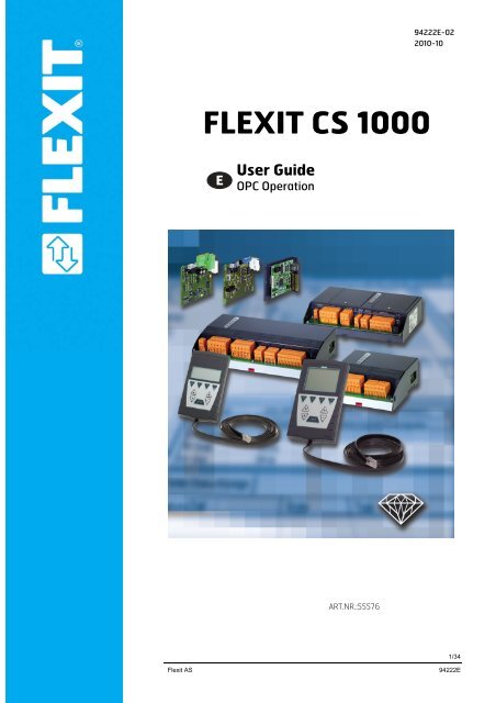
FLEXIT CS 1000<br />
User Guide<br />
<strong>OPC</strong> Operation<br />
ART.NR.:55576<br />
<strong>Flexit</strong> AS <strong>Flexit</strong> AS 94222E<br />
1/<strong>34</strong>
Contents<br />
1 About this Document.....................................................................................4<br />
1.1 Foreword .......................................................................................................4<br />
1.2 Notes on Use ................................................................................................4<br />
1.3 Symbols and Abbreviations...........................................................................4<br />
1.4 Revision History ........................................ Feil! Bokmerke er ikke definert.<br />
2 RCC Communication card ............................................................................5<br />
2.1 What is RCC ...............................................................................................5<br />
2.2 Mounting .......................................................................................................5<br />
2.3 Communication .............................................................................................6<br />
2.3.1 IP address assignment..................................................................................6<br />
2.3.2 Connection of TCP/IP ...................................................................................6<br />
2.3.3 Name resolution (WINS) ...............................................................................6<br />
2.3.4 Connecting to the Web/FTP server via Internet Explorer..............................7<br />
2.4 Update the RCC communication card...........................................................7<br />
2.5 RCC integrated <strong>OPC</strong> server..........................................................................7<br />
3 Remote <strong>OPC</strong>.................................................................................................8<br />
3.1 What is Remote <strong>OPC</strong>..................................................................................8<br />
3.1.1 TCP/IP connection ........................................................................................8<br />
3.1.2 Dial-in/out connection....................................................................................8<br />
3.1.3 Online / Offline handling................................................................................8<br />
3.1.4 Environment file ............................................................................................9<br />
3.2 Install Remote <strong>OPC</strong> ......................................................................................9<br />
4 Configuration...............................................................................................10<br />
4.1 Edit the Environment file .............................................................................10<br />
4.2 Set up TCP/IP connection...........................................................................12<br />
4.3 Set up Modem connection ..........................................................................12<br />
4.3.1 Dial-In connection to the Client PC .............................................................12<br />
4.3.2 Dial-Out Client PC.......................................................................................15<br />
4.3.3 RCC card ....................................................................................................16<br />
4.4 Set up Remote <strong>OPC</strong> service .......................................................................19<br />
4.5 Cache files ..................................................................................................19<br />
4.5.1 Create cache files for Direct links, TCP/IP ..................................................20<br />
4.5.2 Create cache files for Modem links .............................................................20<br />
5 Use Remote <strong>OPC</strong> .......................................................................................21<br />
5.1 <strong>OPC</strong> Client ..................................................................................................21<br />
5.2 Control and status tags for modem connection...........................................21<br />
5.3 Troubleshooting ..........................................................................................22<br />
2/<strong>34</strong><br />
<strong>Flexit</strong> AS<br />
94222E
6 <strong>OPC</strong> Object types and members ................................................................23<br />
6.1.1 Setpoint: Real .............................................................................................23<br />
6.1.2 Setpoint: Enum ...........................................................................................23<br />
6.1.3 Messure (Analog input)...............................................................................23<br />
6.1.4 PosCommand (Analog output) ...................................................................24<br />
6.1.5 Message (Alarms).......................................................................................24<br />
6.1.6 SwitchCommand (Digital outputs) ..............................................................25<br />
6.1.7 Counter .......................................................................................................25<br />
6.1.8 Time Plan: Day ...........................................................................................25<br />
6.1.9 Time Plan: Week.........................................................................................26<br />
6.1.10 Time Plan: Year ..........................................................................................26<br />
6.1.11 LoopController ............................................................................................26<br />
6.1.12 CascadeController ......................................................................................27<br />
7 <strong>OPC</strong> tag translation ....................................................................................28<br />
7.1 Air Handling Units .......................................................................................28<br />
7.1.1 Setpoints, Temperature ..............................................................................28<br />
7.1.2 Setpoints, Pressure / Flow..........................................................................28<br />
7.1.3 General settings / values ............................................................................28<br />
7.1.4 Temperature ...............................................................................................29<br />
7.1.5 Pressure / Flow...........................................................................................29<br />
7.1.6 Analog Inputs, Others .................................................................................29<br />
7.1.7 Analog Outputs ...........................................................................................29<br />
7.1.8 Digital Outputs ............................................................................................30<br />
7.1.9 Digital Inputs ...............................................................................................30<br />
7.1.10 Controllers ..................................................................................................30<br />
7.1.11 Alarms.........................................................................................................31<br />
7.1.12 Alarm delay time .........................................................................................31<br />
7.1.13 Actual Operation mode / Setpoints .............................................................31<br />
7.1.14 Operation mode control ..............................................................................32<br />
7.1.15 Time program..............................................................................................32<br />
7.1.16 General .......................................................................................................32<br />
<strong>Flexit</strong> AS <strong>Flexit</strong> AS 94222E<br />
3/<strong>34</strong>
1 About this Document<br />
1.1 Foreword<br />
Purpose<br />
The purpose of this document is to provide users with a quick and simple means to<br />
familiarize themselves with the configuration of Remote<strong>OPC</strong> and use of the RCC card.<br />
The communication card ACX52.22 is used by the <strong>ACX32</strong> and ACX<strong>34</strong> controller.<br />
1.2 Notes on Use<br />
Target audience<br />
This document is intended for developers who perform commissioning of <strong>OPC</strong>.<br />
1.3 Symbols and Abbreviations<br />
Passages introduced by this symbol indicate a warning to help prevent incorrect<br />
operation.<br />
STOP<br />
Passages introduced by this symbol indicate that the text must be read with special<br />
attention.<br />
Paragraphs with this symbol provide tips.<br />
Abbreviations<br />
Abbreviation<br />
RCC<br />
<strong>OPC</strong><br />
WINS<br />
DHCP<br />
TCP/IP<br />
MAC address<br />
VVS14.0<br />
Dial-In<br />
Dial-Out<br />
Description<br />
Rainbow Communication Card<br />
OLE for Process Control<br />
Windows Internet Naming Service<br />
Dynamic Host Configuration Protocol<br />
Transmission Control Protocol / Internet Protocol<br />
Media Access Control; globally unique, 32 bit "serial number" of the<br />
network card<br />
Valid Version Set<br />
Connection initiated by the RCC card (Incoming call at the PC)<br />
Connection initiated by the client PC<br />
4/<strong>34</strong><br />
<strong>Flexit</strong> AS<br />
94222E
2 RCC Communication card<br />
2.1 What is RCC<br />
General<br />
The RCC card is a communication card that can be used in conjunction with both<br />
SAPHIR primary controllers (<strong>ACX32</strong> and ACX<strong>34</strong>) and contains among other things:<br />
- Web server and FTP server<br />
- TCP/IP<br />
- RAS, Modem connection<br />
The explanations provided in this document are generally based on the basic<br />
configuration of the RCC card.<br />
The term basic configuration refers to the as-delivered state of the ACX52.22 RCC<br />
card.<br />
All information refers to WINDOWS CE image RCCV2_VVS14.0 or higher and are also<br />
recommended for <strong>OPC</strong> communication via Remote<strong>OPC</strong>.<br />
The VVS14.0 RCC card requires the OS3.0 operating system or higher on the SAPHIR<br />
side (see SAPHIR documentation).<br />
2.2 Mounting<br />
Follow the instructions below for mounting the RCC card on the Saphir controller.<br />
LED1<br />
LED2<br />
LED3<br />
X15<br />
Screw for<br />
fixing Card<br />
Modul 1<br />
Com 1<br />
0x4000<br />
X16<br />
Modul 2<br />
Com 2<br />
0x4001<br />
X14<br />
LED4<br />
Relay 8<br />
Relay 1<br />
1<br />
1<br />
1 1 1<br />
X3<br />
X5 X7 X9<br />
X11 S1<br />
1<br />
1 1<br />
1<br />
1 1 1<br />
X1 X4<br />
X12<br />
X13<br />
X6 X8 X10<br />
2 2<br />
Instruction<br />
1. Power off.<br />
2. Dismounting the two forward outside screws on cover with a screw-driver type<br />
Torx 10 or a flat chisel.<br />
Note! Connect yourself to earth to avoid static electricity that could seriously<br />
damage the circuit card.<br />
3. Mount metal fixing supports.<br />
4. For <strong>ACX32</strong>, place the card with belonging cover plate in the “Com 1” slot.<br />
For ACX<strong>34</strong>, place the card with belonging cover plate in the “Com 2” slot.<br />
5. Check that the card is correct connected.<br />
6. Fix card with the screws that are in the kit.<br />
7. Remount the Cover of the controller.<br />
8. Power on.<br />
5/<strong>34</strong><br />
<strong>Flexit</strong> AS<br />
94222E
2.3 Communication<br />
2.3.1 IP address assignment<br />
Network<br />
IP address assignment is either dynamic via DHCP server, or it can be manually<br />
preselected via HMI.<br />
The present IP address can also be read via HMI.<br />
RCC must be properly logged on to the network, or the RCC card cannot be accessed<br />
via TCP/IP. Additionally, all network services, such as the integrated Web server, will<br />
not be accessible.<br />
2.3.2 Connection of TCP/IP<br />
Follow the instructions below to set up the TCP/IP connection.<br />
Instruction<br />
1. Commissioning unit with all settings before starting to install TCP/IP.<br />
2. Attach the network cable to connector X2.<br />
3. Restart by switch off the power.<br />
4. Log in with password (1000 or 2000).<br />
Navigate to menu “Systemparameter – Communication – RCC-Configuration”<br />
Here can the IP-address be read out or changed.<br />
5. If a DHCP-server exists the given IP-address could be read.<br />
6. If an own IP-address should be entered, then enter menu “Change IP”<br />
Change “DHCP” to “Fixed”. Then write the new address. To confirm new<br />
address change “apply” to “Yes”.<br />
7. Restart by switch off the power or perform a software restart.<br />
2.3.3 Name resolution (WINS)<br />
MAC address<br />
Example:<br />
RCC can, however, log on to a WINS server if there is one present on the network.<br />
If logon is successful, the corresponding WINS name can be used to access the device<br />
from that time onwards.<br />
You can easily determine the WINS name from the sticker on the card:<br />
The top number on the sticker is the RCC's MAC address. It always has the form<br />
00 A0 03 FF xxxx, where xxxx is a sequential number.<br />
The WINS name is made up of the prefix SBT_RCC_V2_ and xxxx (i.e. the last four<br />
digits of the MAC address). This name can be change via the integrated Webserver,<br />
and are also visible in the HMI.<br />
The MAC Address on the sticker is 00 A0 03 FF 0AC1. Therefore, the resultant WINS<br />
name is SBT_RCC_V2_0AC1.<br />
The WINS server should be able to resolve a 'ping' on the name, and it should display<br />
the present IP address.<br />
6/<strong>34</strong><br />
<strong>Flexit</strong> AS<br />
94222E
2.3.4 Connecting to the Web/FTP server via Internet Explorer<br />
Web server<br />
Example:<br />
FTP server<br />
Example:<br />
To establish a successful connection to the Web server, use the WINS address or the<br />
IP address.<br />
”http://SBT_RCC_V2_0AC1/” or ”http://146.253.69.197/”<br />
To establish a successful connection to the FTP server, use the same address as for<br />
the web server, but replacing "http://" with "ftp://ADMIN@".<br />
”ftp://ADMIN@SBT_RCC_V2_0AC1/”<br />
Password<br />
FTP Server<br />
Log in with:<br />
User name:<br />
Password:<br />
ADMIN<br />
SBTAdmin!<br />
The same password can also be used for RAS connection to the RCC<br />
The Web server is among other things used to set up the modem communication, this<br />
is described later in this document.<br />
2.4 Update the RCC communication card<br />
Update RCC image<br />
The RCC card can easily be updated with a new version if necessary, ex. if it is an<br />
already installed card with lower VVS. The new image is updated via the TCP/IP<br />
network by starting an exe file on a PC connected to the network and just type in the IP<br />
address or WINS name to the Saphir. After a restart the new image is active, but with<br />
factory settings, so all settings include the IP address must be set again.<br />
2.5 RCC integrated <strong>OPC</strong> server<br />
RCC <strong>OPC</strong> Server<br />
An <strong>OPC</strong> server runs on the RCC (WinCE operating system). This server is not<br />
DCOMM-enabled. A special software component (DeviceCom) has to be installed on a<br />
PC so that an <strong>OPC</strong> client can access the server functionality. This server has been<br />
used as the Saphir <strong>OPC</strong> server until now. This <strong>OPC</strong> server is still available and may be<br />
used as well but the recommendation is to use the new Remote <strong>OPC</strong> instead.<br />
For more information about the integrated <strong>OPC</strong> server there is a separate manual<br />
available.<br />
The Remote<strong>OPC</strong> server functionality described in the following is completely different<br />
from this existing RCC <strong>OPC</strong> server function. The Remote<strong>OPC</strong> server receives the<br />
process data it needs directly via the Saphir controller's Object Handler.<br />
7/<strong>34</strong><br />
<strong>Flexit</strong> AS<br />
94222E
3 Remote <strong>OPC</strong><br />
3.1 What is Remote <strong>OPC</strong><br />
General<br />
The Remote<strong>OPC</strong> application is an <strong>OPC</strong> DA server as well as a management function,<br />
for RCC dial-up connections or/and TCP/IP connections, that runs on the WinXP or<br />
Win2000 operating system in the client PC. The number of dial-up connections that can<br />
be established simultaneously is limited by the hardware used (number of COM ports<br />
with modems). The number of RCC's that can be managed is theoretically unlimited.<br />
The Remote <strong>OPC</strong> is running as a service on the client PC. For each RCC it creates<br />
cache files for fast access and offline browse.<br />
See the PD972-25-009_EN document for more details.<br />
3.1.1 TCP/IP connection<br />
TCP/IP<br />
The Remote <strong>OPC</strong> server can also have access to the RCC via a direct TCP/IP<br />
connection. The direct TCP/IP connection is always online.<br />
Either the IP address or the RCC name can be used.<br />
3.1.2 Dial-in/out connection<br />
Dial-In function<br />
Dial-Out function<br />
An RAS dial-in connection is parameterized on the PC for each COM modem interface.<br />
If a connection is established by an incoming call, the management part of the<br />
Remote<strong>OPC</strong> server compares the RCC's name (e.g. SBT_RCC_V2_ABCD) with the<br />
names of the permitted RCC’s. If the name is known, the server checks whether the<br />
objects in the Saphir controller are known. If so, the <strong>OPC</strong> DA server sets the objects<br />
online. If not, the Saphir controller's Object Handler is interrogated, and the controller is<br />
added to the Remote<strong>OPC</strong> server's namespace. The controller's <strong>OPC</strong> tags are then<br />
available. The tags are valid as long as the connection to the RCC remains established.<br />
The initiator of an active dial-in connection must break the connection again.<br />
A connection must be established to a given Saphir controller if a given event occurs<br />
when there is no online connection. The RCC name is included in the corresponding<br />
<strong>OPC</strong> tag name (event trigger). A dial-up modem connection must be parameterized for<br />
each RCC name on the system. The appropriate connection is activated when the<br />
event occurs.<br />
Since multiple connection names can be parameterized on the "Modem-X" hardware<br />
resource, the resource may already be occupied by another outgoing connection or by<br />
an incoming call from another RCC. In this case, the event must be postponed. When<br />
the defined time (Time_Con_Retry) expires, a new attempt is made to connect to the<br />
respective Saphir controller.<br />
The number of repeat connect attempts is set using the "Con_Retry" parameter.<br />
These parameters are passed in the "Rem<strong>OPC</strong>_Env.csv" environment file.<br />
3.1.3 Online / Offline handling<br />
As long as there is an active connection to one or more of the RCC’s to be managed,<br />
the data of the respective controller(s) is marked as valid. Process data changes are<br />
updated in the server's process image via the COV handling mechanism, and the<br />
clients that are logged on are updated.<br />
As soon as there is no longer an active connection, the tags are marked as offline.<br />
8/<strong>34</strong><br />
<strong>Flexit</strong> AS<br />
94222E
3.1.4 Environment file<br />
The environment file "Rem<strong>OPC</strong>_Env.csv" contains all of the required program<br />
parameters.<br />
These are the connection type (TCP/IP or Modem), timeout period for active dial-up<br />
connections, the connection repeat timeout, the number of dial-up attempts, and all of<br />
the RCC’s to be processed by the server.<br />
The file is stored in the same directory as the Remote<strong>OPC</strong> application. It is read when<br />
the application starts. Only incoming calls from the known RCC’s are accepted by the<br />
Remote<strong>OPC</strong> server for <strong>OPC</strong> tag administration.<br />
The set up of this file is described later in this document.<br />
3.2 Install Remote <strong>OPC</strong><br />
Instruction<br />
The Remote <strong>OPC</strong> server application together with the <strong>OPC</strong> Core Components and the<br />
drivers to communicate with the Saphir has to be installed in the client PC.<br />
Follow the step-by-step instructions below.<br />
1. Install the Scope version 6.10 or higher.<br />
Follow the instructions on the screen.<br />
2. Install the <strong>OPC</strong> Core Components version 3.00 or higher.<br />
Follow the instructions on the screen.<br />
3. Install the Remote <strong>OPC</strong> service version 6.40 or higher.<br />
Follow the instructions on the screen.<br />
4. Check the installation. The following files and folder should be installed in the<br />
default installation path.<br />
9/<strong>34</strong><br />
<strong>Flexit</strong> AS<br />
94222E
4 Configuration<br />
4.1 Edit the Environment file<br />
Each RCC that will be connected to the Remote <strong>OPC</strong> server must be set up in the<br />
environment file. Follow the step-by-step instructions below.<br />
Instruction 1. Open the "Rem<strong>OPC</strong>_Env.csv" environment file with Excel or Notepad.<br />
The file is stored in the same directory as the Remote<strong>OPC</strong> application, default,<br />
C:\Program Files\SBT\Remote<strong>OPC</strong>_Service. This file contains also examples,<br />
so it could be good to copy this file before edit, to keep the examples.<br />
Example:<br />
Example, Excel<br />
Example:<br />
Example, Notepad<br />
Example:<br />
Example of a "Rem<strong>OPC</strong>_Env.csv" file:<br />
3;;;; // Con_Retry<br />
1;;;; // Time_Con_Retry<br />
20;;;; // Con_TimeOut<br />
1;;;; // Trace name: 0=link name, 1=technol. name<br />
192.168.2.111;Test1;D;0x4000; // Testdevice 1 direct link, language COM1<br />
SBT_RCC_V2_0A37;Test2;D;0x4001; // Testdevice 2 direct link, language COM2<br />
SBT_RCC_V2_0A37;Building3C6;D;-1; // Contr. 6 in building 3, direct link, def lang<br />
SBT_RCC_V2_02<strong>34</strong>;Building3C7;M;-1; // Contr. 7 in building 3, modem link, def lang<br />
“;SBT_RCC_V2_0F45”;C1;M;0x4000; // Contr. 1, modem link, Deactivated<br />
Empty line if edit in Notepad<br />
2. Set up line 1 to 4 that is global parameters for modem connection and trace.<br />
Those parameters are valid for all modem connections. Only the first position<br />
in the line is used.<br />
Line 1 - Con_Retry - Number of dial-out attempts<br />
Line 2 - Time_Con_Retry - Time between dial-out attempts<br />
Line 3 - Con_TimeOut - Timeout for active connections<br />
Line 4 - Trace name - Name in trace file, 0=link name, 1= technological name<br />
10/<strong>34</strong><br />
<strong>Flexit</strong> AS<br />
94222E
3. Starting from line 5, all the handled controller are described. Set up an own line<br />
for each RCC with all parameters described below, with a semicolon for<br />
separation. The file must end with an empty line.<br />
o<br />
o<br />
The first parameter for direct links can be either the IP-address or the<br />
RCC-Name. For modem links only the RCC-Name can be used.<br />
(Address resolution).<br />
The second parameter is a freely defined technological name. This<br />
name is used as the root name in the <strong>OPC</strong> item tree-view e.g.<br />
(Building3C7.<strong>ACX32</strong>.SystemClock.Hour).<br />
Depending on parameter on line 4 either the link name e.g. the RCCname<br />
or the technological name will be used in the trace file.<br />
If left empty the technological name will be the same as the link<br />
name/address.<br />
o<br />
o<br />
The third parameter defines the link type.<br />
D - direct link (TCP/IP)<br />
M - modem link.<br />
The last parameter defines the <strong>OPC</strong> tag names and hierarchy. For the<br />
cache file creation a language selection (-1, 0x4000 or 0x4001) can be<br />
used for direct links. Is this parameter missing, the default language -1<br />
will be used. The application implementation language is the default<br />
language.<br />
The language selection via a modem link is done with the virtual tag<br />
“SetLanguageID“. This tag will only be available if no cache files for<br />
the particular link are available.<br />
-1 - Default language (Application language)<br />
0x4000 - COM1 language, Recommended to use for all RCC<br />
0x4001 - COM2 language, Not recommended<br />
4. A comment can be added to each of line after a TAB control character.<br />
A description line ends with the CR control character.<br />
A semicolon at the first entry in a line will disable the handling of this controller.<br />
If edit with NotePad there must also be a “ first and last for the first parameter<br />
e.g. NotePad “;SBT_RCC_V2_0F45”; Excel ;SBT_RCC_V2_0F45;<br />
If more RCC’s are added later in the environment file, then Remote <strong>OPC</strong> service<br />
must be stopped and started again, due to that this file is only read when Remote<br />
<strong>OPC</strong> service starts.<br />
11/<strong>34</strong><br />
<strong>Flexit</strong> AS<br />
94222E
4.2 Set up TCP/IP connection<br />
TCP/IP connection<br />
Set up TCP/IP connection for RCC’s defined with direct link in the environment file. If<br />
no direct links are defined, then continue to the next section.<br />
Remote <strong>OPC</strong> use the TCP/UDP port 4242 for communication and this port must be<br />
open in a firewall.<br />
Instruction 1. Follow the instructions in chapter 2.2 and 2.3 to mount the RCC card and<br />
setup the TCP/IP address if it is not already done.<br />
Example:<br />
2. Ping the RCC card with the WINS or the IP address to test the communication.<br />
(WinStart->Run->Open “CMD”) C:\>ping sbt_rcc_v2_0AC1<br />
No extra configuration is normally needed for TCP/IP connection.<br />
4.3 Set up Modem connection<br />
Modem connection<br />
A modem connection, RAS, has to be set up for each RCC’s defined with modem link<br />
in the environment file. If no modem links are defined, then continue to the next section.<br />
A TCP/IP connection to the RCC card is needed during the configuration, but can<br />
however be just a crossover cable between the RCC and a PC.<br />
Follow all step-by-step instructions below. This guide is for WinXP.<br />
4.3.1 Dial-In connection to the Client PC<br />
An "incoming connection" must be parameterized for each connection to be made from<br />
the outside. No assignment to RCC’s is made.<br />
Instruction 1. Select Start -> Settings -> Network and Dialup connections.<br />
Choose "Create a new connection" and use the network connection wizard.<br />
12/<strong>34</strong><br />
<strong>Flexit</strong> AS<br />
94222E
2. Choose "Set up an advanced connection“.<br />
3. Choose “Accept incoming connections”.<br />
4. Select modem.<br />
13/<strong>34</strong><br />
<strong>Flexit</strong> AS<br />
94222E
5. Choose “Allow virtual private connection”.<br />
6. Add a User with Name and Password.<br />
7. Change the Properties of TCP/IP.<br />
14/<strong>34</strong><br />
<strong>Flexit</strong> AS<br />
94222E
8. Choose your IP range off the RCC Cards.<br />
9. Enter the connection name and finish.<br />
In the Remote<strong>OPC</strong> application, the RAS thread waits for connections via Port 42058<br />
(0xA44A). This port must be open in a firewall.<br />
4.3.2 Dial-Out Client PC<br />
An RAS connection must be parameterized for each RCC to be managed by the<br />
Remote<strong>OPC</strong> server. The connection must have the same name as the RCC to be<br />
contacted (e.g. SBT_RCC_V2_0FDA). This connection name establishes the<br />
relationship between an event and a Saphir controller that is to be notified in the field.<br />
Instruction<br />
1. Select Start -> Settings -> Network and Dialup connections.<br />
Choose "Create a new connection" and use the network connection wizard.<br />
2. Choose "Connect to the work network“ (VPN).<br />
15/<strong>34</strong><br />
<strong>Flexit</strong> AS<br />
94222E
3. Select modem.<br />
4. Enter phone number.<br />
5. Choose “For all users”<br />
6. Define the “Connection Name”, has to be the same name as the RCC to be<br />
contacted and also defined in the environment file e.g. "SBT_RCC_V2_0FDA",<br />
and finish.<br />
The default Username and Password can be used, but it is possible to choose an own<br />
one if needed.<br />
Default Username:<br />
Default Password:<br />
ADMIN<br />
SBTAdmin!<br />
If an event is triggered that causes a change in a tag, the correct connection is<br />
established via the tag name part at the top level (RCC name).<br />
4.3.3 RCC card<br />
The RCC card must be configured for RAS connection. This must be made via TCP/IP.<br />
Instruction<br />
1. Follow the instructions in chapter 2.2 and 2.3 to mount the RCC card and<br />
setup the TCP/IP address if it is not already done.<br />
For a direct RCC to PC connection a fixed TCP/IP address must be set up.<br />
Example: PC RCC<br />
IP 192.168.0.10 192.168.0.20<br />
SN 255.255.255.0 255.255.255.0<br />
GW 192.168.0.1 192.168.0.1<br />
Example:<br />
2. Ping the RCC card with the WINS or the IP address to test the communication.<br />
(WinStart->Run->Open “CMD”) C:\>ping sbt_rcc_v2_0AC1<br />
Example:<br />
Example:<br />
3. Connect to the Web server with the WINS/RCC-name or the IP address via<br />
Internet Explorer.<br />
”http://SBT_RCC_V2_0AC1”<br />
4. Click on the “Open RMS” link.<br />
If the link is missing or there is a login page then fill in the ”/rms/rms.html” in<br />
the address field.<br />
”http://SBT_RCC_V2_0AC1/rms/rms.html”<br />
16/<strong>34</strong><br />
<strong>Flexit</strong> AS<br />
94222E
RCC Version<br />
At the top to the right the actual version for the RCC card is shown. The<br />
version has to be VVS12SP1 or higher but recommended is VVS14 or higher.<br />
The RCC version can also be found in the Registry Manager, key:<br />
HKEY_LOCAL_MACHINE\Ident<br />
RAS settings<br />
5. Click on the ”RAS config” link and “Create a new connection”.<br />
- Define the “Name of Connection”.<br />
- Define the “Phone Number” to the Client PC.<br />
- Define the “User Name”, has to be the same as defined in the client PC.<br />
- Define the “Password”, has to be the same as defiend in the client PC.<br />
- Press the “Submit” button and then the “Back” button.<br />
The User Name and Password has to be the same as defined for the incoming<br />
connection, in the client PC in the User Permission, described before in this<br />
manual.<br />
17/<strong>34</strong><br />
<strong>Flexit</strong> AS<br />
94222E
6. Set up the trigger event and the target Remote <strong>OPC</strong> server.<br />
- Define the “Trigger Member” for alarms, Ex. Unit’, HiearchyNewFault’<br />
- Set the “Trigger AlarmServerId” to 5.<br />
- Set the tic for “Alarm active state”, and the other tics if needed.<br />
- Define the “<strong>OPC</strong>AlarmServerName”, Use the IP-number defined in the Client<br />
PC for incoming calls.<br />
- Set the “Port” to 42058.<br />
- Press the “Update all Values” button.<br />
Any changes on the RAS Configuration Page needs a reset of the RCC card.<br />
Own User name and Password can be set up at the “Server config” page. The same<br />
User name and Password must then also be used for the outgoing connection in the<br />
client PC.<br />
18/<strong>34</strong><br />
<strong>Flexit</strong> AS<br />
94222E
4.4 Set up Remote <strong>OPC</strong> service<br />
Remote <strong>OPC</strong> service<br />
Remote <strong>OPC</strong> is running as a service and after installation the “Startup type” is set to<br />
“Manual”. The service handler is used to manage Remote <strong>OPC</strong> and change the<br />
“Startup type” to “Automatic” or just handle the manual start and stop.<br />
Instruction 1. Select Start -> Settings -> Control Panel -> Administrative Tools -> Services.<br />
2. The service properties can be changed with a right click on the Remote<strong>OPC</strong><br />
application.<br />
Start the Remote<strong>OPC</strong> server either manually, or set the “Startup type” to<br />
“Automatic”, so the application starts with a system boot up sequence.<br />
4.5 Cache files<br />
Cache files<br />
For each RCC Remote <strong>OPC</strong> creates cache files for fast access and offline browse.<br />
After the first installation of the Remote<strong>OPC</strong> server, no cache files are available.<br />
Cache files are created, for every new RCC in the environment file, at every startup of<br />
Remote <strong>OPC</strong>. Excisting cache files are resistant and are not read in again.<br />
If more RCC’s are added later in the environment file, then Remote <strong>OPC</strong> service must<br />
be stopped and started again, due to that this file is only read when Remote <strong>OPC</strong><br />
service starts<br />
19/<strong>34</strong><br />
<strong>Flexit</strong> AS<br />
94222E
Three files must be created for every controller and the files is found in the default path<br />
“C:\Program Files\SBT\Remote<strong>OPC</strong>_Service\CacheFiles”.<br />
They are named either by the IP-Address or the RCC-Name with different extensions.<br />
For the IP 149.246.39.2<strong>34</strong> the files<br />
149.246.39.2<strong>34</strong>_ObjData.bin<br />
149.246.39.2<strong>34</strong>_TypeDesc.bin<br />
149.246.39.2<strong>34</strong>_TypeInfo.bin<br />
are created,<br />
or for the link SBT_RCC_V2_04DA the files<br />
SBT_RCC_V2_04DA_ObjData.bin<br />
SBT_RCC_V2_04DA_TypeDesc.bin<br />
SBT_RCC_V2_04DA_TypeInfo.bin<br />
are created.<br />
4.5.1 Create cache files for Direct links, TCP/IP<br />
Be sure the controller is connected to the LAN and a ping to the controller is<br />
possible.<br />
When the Remote<strong>OPC</strong> server is started, the cache files for all direct linked<br />
controllers will be created. This may take a few seconds.<br />
4.5.2 Create cache files for Modem links<br />
Start an <strong>OPC</strong> client (e.g. Softing democlient) and connect to the Remote <strong>OPC</strong><br />
Server.<br />
For a modem link without cache files, only 5 virtual tags are available.<br />
Please set the tag “ManualConnect” = 1 and your PC will dial out to connect to<br />
the selected controller<br />
After the connection is established, the cache files will be created. As soon as<br />
all three files are created, the line will ring off.<br />
Repeat it for all modem links without cache files.<br />
After all modem link cache files are available, you have to restart the<br />
Remote<strong>OPC</strong> Server ones.<br />
This procedure has to be done just for the very first time to get the cache files, or in<br />
case for a certain controller, when a new application has been loaded.<br />
In the second case the old cache files must be removed manually before connecting to<br />
the controller with a new application running.<br />
20/<strong>34</strong><br />
<strong>Flexit</strong> AS<br />
94222E
5 Use Remote <strong>OPC</strong><br />
5.1 <strong>OPC</strong> Client<br />
When all the cache files are available it is possible to browse with an <strong>OPC</strong>-Client the<br />
object tree of all the known controller, even they are offline.<br />
After selecting the wanted tags the values are updated as the controller is online.<br />
5.2 Control and status tags for modem connection<br />
Three virtual control variables are added to the object tree of a Saphir controller.<br />
Auto_Connect:<br />
The "Auto_Connect" control variable is a Boolean value. If the variable is set to TRUE,<br />
a connection to the Saphir controller is automatically established in case of write<br />
access to a tag when there is no online connection to the controller. The connection<br />
remains active for the timeout period. The timeout time is re-triggered by each write<br />
access.<br />
If a connection cannot be established, the dial-out attempt is repeated after the<br />
"Time_Con_Retry" timeout period. The number of repeat connect attempts is limited by<br />
the "Con_Retry" parameter.<br />
21/<strong>34</strong><br />
<strong>Flexit</strong> AS<br />
94222E
Manual_Connect:<br />
The "Manual_Connect" control variable is a Boolean value. If the variable is set to<br />
TRUE, a connection is established to the Saphir controller. An existing connection is<br />
not interrupted, or a connection attempt is not cancelled until the variable changes to<br />
FALSE. If a connection cannot be established, the dial-out attempt is repeated after the<br />
"Time_Con_Retry" timeout period. The number of repeat connect attempts is not limited<br />
by the "Con_Retry" parameter.<br />
Status_Connect:<br />
The "Status_Connect" status variable is a Boolean value. It indicates whether there is<br />
an active dial-up connection to the respective controller (TRUE == Online).<br />
5.3 Troubleshooting<br />
General<br />
Network<br />
RCC version<br />
Remote <strong>OPC</strong><br />
Web pages<br />
Modem<br />
Other<br />
<br />
<br />
<br />
<br />
<br />
<br />
<br />
<br />
<br />
<br />
<br />
The RCC card or the Saphir must be restarted after IP and RAS configuration.<br />
(hardware or software restart is possible).<br />
When use of Fixed IP address, change parameter DHCP to Fixed, change IP<br />
address, confirm by change “apply” to “Yes” and restart the controller.<br />
Try to ping the controller if the communication is not working. If the ping fails<br />
something is wrong in the network or the IP settings.<br />
Check that the defined UDP port is open in the firewall.<br />
The version has to be VVS12SP1 or higher for Remote <strong>OPC</strong> to work.<br />
The RCC version can be found under “Treeview/Device/Version”.<br />
The opcproxy.dll must be registered. Remote <strong>OPC</strong> are using <strong>OPC</strong> v3 and<br />
some clients don’t have support for v3, then the opcproxy.dll must be change<br />
to an older one.<br />
If Remote <strong>OPC</strong> don’t create cache file for the last RCC in the environment files<br />
it’s probably not a CR after that line, there must be an empty line at the end of<br />
the file.<br />
Direct link RCC’s that are not used (not online) should be deactivated or<br />
deleted in the environment file and the cache file should be deleted as well.<br />
If there is another start/front page than the default, it is probably a compact<br />
flash memory installed at the RCC card. Remove the memory or type in the<br />
direct address to the actual page.<br />
GSM modems should NOT be used, due to that the communication speed is to<br />
low.<br />
New Saphir controllers may have a time scheduler for BACnet and that one is<br />
not compatible with <strong>OPC</strong>. Anyhow, the old time scheduler with <strong>OPC</strong><br />
compabillity is often still available in the controller after a reconfiguration.<br />
22/<strong>34</strong><br />
<strong>Flexit</strong> AS<br />
94222E
6 <strong>OPC</strong> Object types and members<br />
This chapter explains the Object handler and the members that can be used for each<br />
object type. Recommended members to use with <strong>OPC</strong> are marked, other members<br />
should be used with carefulness, especially the “ValueDectection” member.<br />
6.1.1 Setpoint: Real<br />
MemberID Member Name Description<br />
0x0000 UserAccess Specifies operation privilege.<br />
The member setpoint (0x0003) can only be changed in "Man".<br />
0x0001 HighLimit High input limit for member setpoint (0x0003)<br />
0x0002 LowLimit Low input limit for member setpoint (0x0003)<br />
0x0003 Setpoint Valid setpoint<br />
6.1.2 Setpoint: Enum<br />
MemberID Member Name Description<br />
0x0000 UserAccess Specifies operation privilege.<br />
The member setpoint (0x0002) can only be changed in "Man".<br />
0x0001 HighLimit High input limit for member setpoint (0x0002)<br />
0x0002 Setpoint Valid setpoint<br />
6.1.3 Messure (Analog input)<br />
MemberID Member Name Description<br />
0x0000 ValueDetection This parameter can be used to deactivate the detection of<br />
parameters 0x1200 and 0x0009.<br />
These members are then also writeable.<br />
0x1200 ValueFault "Active" indicates that this measured value is in an error state<br />
0x0001 HighLimit1Active Indicates that the value is above the high alarm limit<br />
(0x000A).<br />
0x0002 HighLimit2Active Indicates that the value is above the high warning limit<br />
(0x000B).<br />
0x0003 LowLimit2Active Indicates that the value is below the low warning limit<br />
(0x000C).<br />
0x0004 LowLimit1Active Indicates that the value is below the low alarm limit<br />
(0x000D).<br />
0x0005 SlidingLimits As long as this parameter is active, the limits are read<br />
cyclically via the "HIL", "HIWL", "LOWL" and "LOL" inputs.<br />
The corresponding members can then not be overwritten<br />
with the ObjectHandler.<br />
0x0006 FaultStored As long as this parameter is active, the fault (0x1200) is<br />
stored, i.e. it must be reset with the appropriate message<br />
class (0x0007).<br />
0x0007 MessageClass Fault message class (0x1200)<br />
0x0008 SuppressLimitCheck This member can be used to suppress limit value<br />
monitoring.<br />
As long as this parameter is active, out-of-limits conditions<br />
do not produce a database entry, and the parameters<br />
(0x0001…0x0004) are set to zero.<br />
0x0009 PresentValue This parameter signalizes the measured value without an<br />
error.<br />
0x000A HighLimit1 High alarm limit<br />
0x000B HighLimit2 High warning limit<br />
0x000C LowLimit2 Low warning limit<br />
0x000D LowLimit1 Low alarm limit<br />
0x000E InputCorrection Offset for input value connection.<br />
It is added to the physical input value, then signalized at<br />
member 0x0009.<br />
0x000F PT1Filter Delay time in seconds of the PT1-element for smoothing.<br />
As long as the parameter is set to zero, no smoothing occurs.<br />
23/<strong>34</strong><br />
<strong>Flexit</strong> AS<br />
94222E
6.1.4 PosCommand (Analog output)<br />
MemberID Member Name Description<br />
0x0000 ValueDetection This parameter can be used to deactivate the detection of<br />
present position 0x000A and fault 0x0001.<br />
In this case, member fault is also writeable.<br />
The present position 0x000A is set equal to the setpoint<br />
position 0x000D.<br />
0x0001 Fault Indicates the stored fault.<br />
0x0002 RemoteActuating If inactive, the controller has no access to the hardware.<br />
The present position is indicated in each case.<br />
The "POSN" output is set to 0.<br />
0x0003 ApplicationControl Indicates that the step setpoint (0x000B) is specified by the<br />
application in automatic mode (0x0003).<br />
0x0004 CTRLLoopLock Indicates that the control element is not available to the<br />
controller.<br />
0x0005 UserAccess Specifies operation privilege. The member position setpoint<br />
(0x000D) can only be changed in "Man". 0=Hand, 1=Auto<br />
0x0006 Forcing Indicates that override control is active.<br />
0x0007 MessageClass Fault message class (0x0001)<br />
0x0008 PresentValue Control element feedback signal<br />
0x0009 HighLimit The high control limit of the control element can be entered<br />
here.<br />
0x000A LowLimit Low control limit of the control element<br />
0x000B Setpoint Indicates the present position setpoint.<br />
Can be changed by the ObjectHandler if 0x0003 = TRUE.<br />
0x000C Sensitivity Accuracy of the control element.<br />
Only setpoint changes that are greater than this member are<br />
passed to the "POSN" output.<br />
0x000D Output Type Indicates the control signal type:<br />
0 = analog output, analog feedback signal<br />
1 = digital output, feedback signal calculated using actuating time<br />
2 = digital output, analog feedback signal<br />
0x000E Digital:OpenTime The time the valve requires to fully open.<br />
0x000F Digital:CloseTime The time the valve requires to fully close.<br />
0x0010 Digital:LongSync Default value FALSE:<br />
If TRUE, the outputs remain active at the end positions.<br />
If FALSE, the signal only remains active for 3x the time.<br />
6.1.5 Message (Alarms)<br />
MemberID Member Name Description<br />
0x0000 ValueDetection This parameter can be used to deactivate the detection of<br />
parameter 0x0001.<br />
This member is then also writeable.<br />
0x0001 CurrentState "Active" means that this status message is active:<br />
State text from member 0x1101<br />
0x0002 StoredState Indicates the stored state:<br />
State text from member 0x1101<br />
0x0003 WorkingContact "Active" means normally open contact:<br />
Otherwise normally closed contact, i.e. a signal at the "DI"<br />
input is the good state<br />
0x0004 MessageClass Fault message class (0x0002)<br />
0x0005 FaultStored As long as this parameter is active, the fault (0x0002) is<br />
stored, i.e. it must be reset with the appropriate message<br />
class (0x0004).<br />
0x0006 DelayEnable Delay in seconds after enable<br />
0x0007 DelayMessage Minimum time that a fault must be present before a message<br />
is actually generated (flutter protection).<br />
24/<strong>34</strong><br />
<strong>Flexit</strong> AS<br />
94222E
6.1.6 SwitchCommand (Digital outputs)<br />
MemberID Member Name Description<br />
0x0000 ValueDetection This parameter can be used to deactivate the detection of<br />
PresentStage (0x000A) and Fault (0x0001) parameters.<br />
In this case, the Fault member is also writeable.<br />
PresentStage (0x000A) is set equal to SetpointStage (0x000B).<br />
0x0001 Fault Indicates a fault. Is generated if the PresentStage fails to<br />
follow the SetpointStage within the runtime (DELFB).<br />
0x0002 RemoteActuating If inactive, the controller has no access to the hardware.<br />
The present state is displayed, and feedback signal<br />
monitoring is suppressed (0x0001).<br />
The "COM" output is set to step 0.<br />
0x0003 UserAccess Specifies operation privilege. The member step setpoint<br />
(0x000B) can only be changed in "Man". 0=Hand, 1=Auto<br />
0x0004 SupressFeedback Suppresses runtime monitoring (0x0001)<br />
0x0005 Forcing Indicates that override control is active.<br />
The application specifies the step setpoint.<br />
0x0006 Optimizing Activates and deactivates the optimization function.<br />
0x0007 MessageClass Fault message class (0x0001)<br />
0x0008 ApplicationControl Indicates that the step setpoint (0x000B) is specified by the<br />
application in automatic mode (0x0003).<br />
0x0009 OptDirectionHigh Optimization is achieved by stepping up.<br />
0x000A PresentStage Switching command feedback signal<br />
0x000B SetpointStage Indicates the present step setpoint. Can be changed by the<br />
ObjectHandler if 0x0003 = TRUE.<br />
0x000C OptimizeStage Specifies the optimization step.<br />
0x000D MaxStage Maximum permissible switching step.<br />
1 signifies, for example 0=off and 1=Step 1 is permitted.<br />
6.1.7 Counter<br />
MemberID Member Name Description<br />
0x0000 ValueDetection This parameter can be used to deactivate the detection of<br />
parameter 0x0001.<br />
This member is then also writeable.<br />
0x0001 ValueFault Active indicates that this counter value is in an error state.<br />
0x0002 HighLimitActive Indicates that the value is above the alarm limit (0x000E).<br />
0x0003 CountValueLost Indicates that the counter value has missed pulses.<br />
0x0004 UserAccess Must be set to "Man" in order to delete (0x0006) or set<br />
(0x0007) the counter value.<br />
Always set to "Man" by default. 0=Hand, 1=Auto<br />
0x0005 OverflowCounter Indicates an overflow of the internal counter.<br />
0x0006 EraseCounter Sets the counter to zero.<br />
0x0007 SetCounter Adds the offset (0x000C) to the present counter value<br />
(0x000B)<br />
0x0008 MessageClass Fault message class (0x0001)<br />
0x0009 Me.ClassHighLimit Limit for the resultant value (0x000A)<br />
0x000A PresentValue Resultant value of the counter (dimensioned)<br />
0x000B CounterValue Internal pulse counter value<br />
0x000C OffsetCounter Offset that is added to the present counter value (0x000B)<br />
during setting (0x0007)<br />
0x000D ImpulseValue Pulse counter. The resultant value 0x000A is calculated from<br />
this value and member 0x000B.<br />
0x000E HighLimit Resultant value high limit<br />
6.1.8 Time Plan: Day<br />
MemberID Member Name Description<br />
0x0000 AggregateName Name of the controlled unit<br />
0x0001 Valid TRUE if the schedule is valid and active<br />
0x0002 Hour Switching hour<br />
0x0003 Minute Switching minute<br />
0x0004 Stage Value that should apply from the point in time indicated<br />
25/<strong>34</strong><br />
<strong>Flexit</strong> AS<br />
94222E
6.1.9 Time Plan: Week<br />
MemberID Member Name Description<br />
0x0000 AggregateName Name of the controlled unit<br />
0x0001 Valid TRUE if the schedule is valid and active<br />
0x0002 StartDay Starting point: day of week (0=Mon … 6=Sun)<br />
0x0003 StartHour Starting point: hour<br />
0x0004 StartMin Starting point: minute<br />
0x0005 EndDay End point: day of week (0=Mon … 6=Sun)<br />
0x0006 EndHour End point: hour<br />
0x0007 EndMin End point: minute<br />
0x0008 Stage Value that should apply during the period indicated<br />
6.1.10 Time Plan: Year<br />
MemberID Member Name Description<br />
0x0000 AggregateName Name of the controlled unit<br />
0x0001 Valid TRUE if the schedule is valid and active<br />
0x0002 StartDay Starting point: day<br />
0x0003 StartMonth Starting point: month<br />
0x0004 StartHour Starting point: hour<br />
0x0005 StartMin Starting point: minute<br />
0x0006 EndDay End point: day<br />
0x0007 EndMonth End point: month<br />
0x0008 EndHour End point: hour<br />
0x0009 EndMin End point: minute<br />
0x000A Stage Value that should apply during the period indicated<br />
6.1.11 LoopController<br />
MemberID Member Name Description<br />
0x0000 Enable Enables the controller for closed-loop control.<br />
0x0001 Fault Indicates the stored fault.<br />
0x0002 MessageClass Fault message class (0x0001)<br />
0x0003 Hand If this member is set, the controller is deactivated.<br />
0x0004 InvertProportional Used to invert the control algorithm. Additionally, the<br />
behavior in the disabled state also changes.<br />
Can be used for limiting controllers, for example.<br />
0x0005 Status Indicates the controller’s status.<br />
If multiple states are active, the priority of the listed numbers<br />
applies, i.e. the highest priority wins.<br />
Value Meaning Priority<br />
0 Controller disabled 5<br />
1 Controller at high limit 3<br />
2 Controller at low limit 2<br />
3 Within control range 5<br />
4 Control element not available 4<br />
0x0006 PresentValue Present value<br />
0x0007 Setpoint Setpoint<br />
0x0008 CTRLOutput Present requested position setpoint of the control element<br />
(controller output)<br />
0x0009 ProportionalFactor Proportional factor (gain) of the PID-controller<br />
0x000A IntegralFactor Integral factor; integral-action time in seconds<br />
(0=I-component deactivated)<br />
0x000B DifferentialFactor Differential factor in seconds (0=D-component deactivated)<br />
0x000C HighLimit Maximum permissible positioning signal output value<br />
0x000D LowLimit Minimum permissible positioning signal output value<br />
26/<strong>34</strong><br />
<strong>Flexit</strong> AS<br />
94222E
6.1.12 CascadeController<br />
MemberID Member Name Description<br />
0x0000 Enable Enables the controller for closed-loop control<br />
0x0001 Fault Indicates the stored fault<br />
0x0002 ApplicationControl Indicates that the setpoint (0x0009) is specified by the<br />
application in automatic mode (0x0003).<br />
0x0003 UserAccess Specifies operation privilege. The member setpoint (0x0009)<br />
can only be changed in “Man”.<br />
0x0004 MessageClass Fault message class (0x0001)<br />
0x0005 Hand If this member is set, the controller is deactivated.<br />
0x0006 Status Indicates the controller’s status. If multiple states are active,<br />
the priority of the listed numbers applies, i.e. the highest<br />
priority wins.<br />
Value Meaning Priority<br />
5 Controller disabled 5<br />
6 Controller at high limit 3<br />
7 Controller at low limit 2<br />
8 Within control range 5<br />
9 Control element not available 4<br />
0x0007 PresentValue Present value<br />
0x0008 Setpoint Valid setpoint<br />
0x0009 BasicSetpoint Basic setpoint; can be changed by the ObjectHandler if<br />
0x0002 = TRUE.<br />
0x000A CTRLOutput Present requested position setpoint of the control element<br />
(controller output)<br />
0x000B ProportionalFactor Proportional factor (gain) of the PID-controller<br />
0x000C IntegralFactor Integral factor; integral-action time in seconds<br />
(0=I-component deactivated)<br />
0x000D WorkingPointDiff Operating point difference<br />
0x000E HighLimit Maximum permissible positioning signal output value<br />
0x000F LowLimit Minimum permissible positioning signal output value<br />
0x0010 DeadZone Dead zone between the upper and lower setpoints.<br />
Calculated from the basic setpoint 0x0009.<br />
27/<strong>34</strong><br />
<strong>Flexit</strong> AS<br />
94222E
7 <strong>OPC</strong> tag translation<br />
7.1 Air Handling Units<br />
<strong>OPC</strong> tags for Siemens LB20 application.<br />
7.1.1 Setpoints, Temperature<br />
<strong>OPC</strong> tag name Description Object type<br />
TSC1<br />
HeatingComfort<br />
TSC2 CoolingComfort Setpoint: Real<br />
TSE1 HeatingEconomy “<br />
TSE2<br />
CoolingEconomy<br />
GE46 Setpoint HRC frost protection Setpoint: Real<br />
TS80 Setpoint frostprotection, operating temperature “<br />
TS81<br />
Setpoint frostprotection, keeping warm<br />
7.1.2 Setpoints, Pressure / Flow<br />
<strong>OPC</strong> tag name Description Object type<br />
VS10 Setpoint flow supply air lowspeed Setpoint: Real<br />
VS11 Setpoint flow supply air highspeed “<br />
VS20<br />
Setpoint flow exhaust air lowspeed<br />
VS21<br />
Setpoint flow exhaust air highspeed<br />
7.1.3 General settings / values<br />
<strong>OPC</strong> tag name Description Object type<br />
GE01 FrostAlarmValue Setpoint:Real/Enum<br />
GE22 RoomSetpoint “<br />
GE28<br />
ExtendRunTime<br />
GE30<br />
LimitClgUnoccupied<br />
GE31<br />
LimitHtgUnoccupied<br />
GE39<br />
SupTOAComp<br />
GE42<br />
TempAlarmSet<br />
GE43<br />
DeltaHeating<br />
GE44<br />
DeltaCooling<br />
GE46<br />
HRFrostSetpoint<br />
GE59<br />
HREff_Alm<br />
GE61<br />
HRC_Efficiency<br />
GE62<br />
CompStartPoint<br />
GE63<br />
CompStopPoint<br />
GE64<br />
VolSuLoDelta<br />
GE65<br />
VolSuHiDelta<br />
GE66<br />
VolExLoDelta<br />
GE67<br />
VolExHiDelta<br />
GE68<br />
PressSuLoDelta<br />
GE69<br />
PressSuHiDelta<br />
GE70<br />
PressExLoDelta<br />
GE71<br />
PressExHiDelta<br />
GE72<br />
VolAlarmSet<br />
GE73<br />
PressAlarmSet<br />
G121<br />
CancelExtendOp<br />
G122<br />
ForcedRunTime<br />
G123<br />
SupMinLimit<br />
G124<br />
SupMaxLimit<br />
G125<br />
ExtMinLimit<br />
G126<br />
ExtMaxLimit<br />
G127<br />
CancelForcedOp<br />
G128<br />
SupFiltAlm<br />
G129<br />
ExtFiltAlm<br />
28/<strong>34</strong><br />
<strong>Flexit</strong> AS<br />
94222E
7.1.4 Temperature<br />
<strong>OPC</strong> tag name Description Object type<br />
GT10 SupplyAirTemp Messure<br />
GT30 Room/ExtrTemp “<br />
GT41<br />
HRCFrostTemp<br />
GT80<br />
WaterFrostTemp<br />
GT90<br />
OutTemp<br />
GT10<br />
SupplyAirTemp<br />
7.1.5 Pressure / Flow<br />
<strong>OPC</strong> tag name Description Object type<br />
GF10 SupplyVol Messure<br />
GF20 ExtractVol “<br />
GP10<br />
SupplyPressure<br />
GP15<br />
SupFilterPress<br />
GP20<br />
ExtractPressure<br />
GP25<br />
ExtFilterPress<br />
7.1.6 Analog Inputs, Others<br />
<strong>OPC</strong> tag name Description Object type<br />
GQ10 SupplyCO2 Messure<br />
GQ20<br />
ExtractCO2<br />
7.1.7 Analog Outputs<br />
<strong>OPC</strong> tag name Description Object type<br />
SV10 Heating PosCommand<br />
SV20 Cooling “<br />
HD10<br />
Heating recovery (HRC)<br />
FO10<br />
Frequency converter Supply fan<br />
FO20<br />
Frequency converter Exhaust fan<br />
29/<strong>34</strong><br />
<strong>Flexit</strong> AS<br />
94222E
7.1.8 Digital Outputs<br />
<strong>OPC</strong> tag name Description Object type<br />
ST10 Out door damper SwitchCommand<br />
OP02 Fan “<br />
DX10 DX 1<br />
DX20 DX 2<br />
EB12<br />
ElecHeaterStage2<br />
EB13<br />
ElecHeaterStage3<br />
HD10<br />
HeatRecovery<br />
7.1.9 Digital Inputs<br />
<strong>OPC</strong> tag name Description Object type<br />
Not implemented<br />
Setpoint: Enum<br />
7.1.10 Controllers<br />
<strong>OPC</strong> tag name Description Object type<br />
Not implemented<br />
LoopController<br />
30/<strong>34</strong><br />
<strong>Flexit</strong> AS<br />
94222E
7.1.11 Alarms<br />
<strong>OPC</strong> tag name Description Object type<br />
AL00 Reset Alarms Setpoint: Enum<br />
AL01 LmFireSmoke Message<br />
AL02 LmRotorGuardAlarm “<br />
AL06<br />
LmErrorSupplyFu<br />
AL07<br />
LmErrorExtractFU<br />
AL08<br />
LmSensorError<br />
AL09<br />
LmTempAlarm<br />
AL10<br />
LmFrostAlarm<br />
AL11<br />
LmUnitOverRideAlarm<br />
AL13<br />
LmHRCFrostAlarm<br />
AL14<br />
LmHRC_EffAlarm<br />
AL15<br />
B_Alarm<br />
AL16<br />
A_Alarm<br />
AL27<br />
LmFanCommonFault<br />
AL28<br />
LmElecHtrO/H<br />
AL29<br />
LmElecHtrFire<br />
AL30 LmSupFilter Message<br />
AL31<br />
LmExtFilter<br />
7.1.12 Alarm delay time<br />
<strong>OPC</strong> tag name Description Object type<br />
Not used<br />
Setpoint: Real<br />
7.1.13 Actual Operation mode / Setpoints<br />
<strong>OPC</strong> tag name Description Object type<br />
OP01 StartStop Setpoint: Enum<br />
OP02 Fan “<br />
OP03<br />
ExtendedOp<br />
OP04 TempCtlrType Messure<br />
OP06 ActualSetpoint Setpoint: Enum<br />
OP07 OP_Mode Messure<br />
OP08 ActualStpSu Setpoint real<br />
OP09<br />
ActualStpEx<br />
OP12 ExternalStop Setpoint: Enum<br />
OP16<br />
ForcedOp<br />
OP17<br />
SupFanMode:<br />
OP18<br />
ExtFanMode:<br />
31/<strong>34</strong><br />
<strong>Flexit</strong> AS<br />
94222E
7.1.14 Operation mode control<br />
<strong>OPC</strong> tag name Description Object type<br />
TB01<br />
BMS override timeprogram<br />
Setpoint: Enum<br />
0 = Internal TSP, 1= Off, 2 = Eco St1<br />
3 = Eco St2, 4 = Comf St1, 5 = Comf St2<br />
TB02<br />
Saphir override timeprogram<br />
“<br />
0 = Internal TSP, 1= Off, 2 = Eco St1<br />
3 = Eco St2, 4 = Comf St1, 5 = Comf St2<br />
TB03<br />
Emegency stop via communication<br />
0 = Off/Normal, 1= Stop<br />
7.1.15 Time program<br />
<strong>OPC</strong> tag name Description Object type<br />
TD0x<br />
Air handling unit, dayplan<br />
Time plan<br />
0 = Off, 1 = Eco St1, 2 = Eco St2<br />
3 = Comf St1, 4 = Comf St2<br />
TW0x Air handling unit, weekplan “<br />
TY0x<br />
Air handling unit, yearplan<br />
SD0x<br />
SMS alarm routing, dayplan<br />
0 = Off, 1 = Tel1, 2 = Tel2, 3 = Tel3, 4 = Tel4<br />
SW0x<br />
SMS alarm routing, weekplan<br />
SY0x<br />
SMS alarm routing, yearplan<br />
ED0x<br />
External device, dayplan<br />
0 = Off, 1 = On<br />
EW0x<br />
External device, weekplan<br />
7.1.16 General<br />
<strong>OPC</strong> tag name Description Object type<br />
AC01<br />
Air conditioning<br />
AHU1<br />
Air handling unit<br />
0 = Off, 1 = Eco St1, 2 = Eco St2<br />
3 = Comf St1, 4 = Comf St2<br />
Unit<br />
32/<strong>34</strong><br />
<strong>Flexit</strong> AS<br />
94222E
Index<br />
Time program Week ............................................27<br />
A<br />
Time program Year..............................................27<br />
Abbreviations ..............................................................5 Object types ..............................................................24<br />
About this document ...................................................5 <strong>OPC</strong> Clients ..............................................................22<br />
<strong>OPC</strong> Tags .................................................................29<br />
C<br />
Alarms..................................................................32<br />
Configure Analog inputs .......................................................30<br />
Cache files...........................................................20<br />
Analog outputs.....................................................30<br />
Modem connection ..............................................13 Controllers ...........................................................31<br />
Remote <strong>OPC</strong> service...........................................20 Digital inputs ........................................................31<br />
TCP/IP connection...............................................13 Digital outputs ......................................................31<br />
Configure General ................................................................33<br />
Environment file...................................................11 Operation modes .................................................32<br />
IP ...........................................................................7<br />
Setpoints..............................................................29<br />
Connect.......................................................................7<br />
Settings................................................................29<br />
Control tags, modem connection ..............................22 Time program ......................................................33<br />
D<br />
P<br />
DHCP..........................................................................7 Password ....................................................................8<br />
F<br />
R<br />
FTP server ..................................................................8 RCC integrated <strong>OPC</strong> server........................................8<br />
RCC Version .............................................................18<br />
G<br />
Remote <strong>OPC</strong><br />
General introduction....................................................6 Environment file ...................................................10<br />
General ..................................................................9<br />
I<br />
Install ...................................................................10<br />
IP address...................................................................7<br />
Modem Dial-in/out..................................................9<br />
Online/Offline handling ..........................................9<br />
M<br />
TCP/IP connection.................................................9<br />
MAC address ..............................................................7<br />
Members ...................................................................24<br />
S<br />
Mounting communication card ....................................6<br />
Symbols ......................................................................5<br />
N<br />
Name resolution (WINS) .............................................7<br />
T<br />
Tag translation ..........................................................29<br />
Troubleshooting ........................................................23<br />
O<br />
Object<br />
U<br />
Alarm ...................................................................25<br />
Update RCC image .....................................................8<br />
Analog input.........................................................24<br />
Analog output ......................................................25 V<br />
Cascadecontroller................................................28 Virtual control ............................................................22<br />
Controller .............................................................27<br />
Counter................................................................26 W<br />
Digital output........................................................26<br />
Setpoints..............................................................24<br />
Time program Day...............................................26<br />
Webserver...................................................................8<br />
33/<strong>34</strong><br />
Fllexit AS<br />
94222E
<strong>Flexit</strong> AS<br />
94222E


