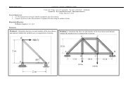
Vulcraft Steel Joists and Joist Girders Catalog - Sites at Lafayette
Vulcraft Steel Joists and Joist Girders Catalog - Sites at Lafayette
Vulcraft Steel Joists and Joist Girders Catalog - Sites at Lafayette

You also want an ePaper? Increase the reach of your titles
YUMPU automatically turns print PDFs into web optimized ePapers that Google loves.
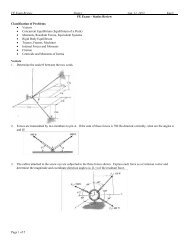
STANDARD SPECIFICATIONS / FOR OPEN WEB STEEL JOISTS, K -SERIES<br />
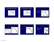
Bridging shall support the top chords against l<strong>at</strong>eral<br />
movement during the construction period <strong>and</strong> shall hold<br />
the steel joists in the approxim<strong>at</strong>e position as shown on<br />
the plans.<br />
The ends of all bridging lines termin<strong>at</strong>ing <strong>at</strong> walls or<br />
beams shall be anchored thereto.<br />
5.6 END ANCHORAGE<br />
( a ) M a s o n ry <strong>and</strong> Concre t e<br />
Ends of K-Series <strong><strong>Joist</strong>s</strong> resting on steel bearing<br />
pl<strong>at</strong>es on masonry or structural concrete shall be<br />
<strong>at</strong>tached thereto with a minimum of two 1 ⁄8 inch (3<br />
mm) fillet welds 1 inch (25 mm) long, or with two 1 ⁄2<br />
inch (13 mm) bolts, or with the combin<strong>at</strong>ion of one 1 ⁄2<br />
inch (13 mm) bolt <strong>and</strong> one 1 ⁄8 inch (3 mm) fillet weld<br />
1 inch (25 mm) long.<br />
( b ) S t e e l<br />
Ends of K-Series <strong><strong>Joist</strong>s</strong> resting on steel supports<br />
shall be <strong>at</strong>tached thereto with a minimum of two 1 ⁄8<br />
inch (3 mm) fillet welds 1 inch (25 mm) long, or with<br />
two 1 ⁄2 inch (13 mm) bolts, or with the combin<strong>at</strong>ion of<br />
one 1 ⁄2 inch (13 mm) bolt <strong>and</strong> one 1 ⁄8 inch (3 mm) fillet<br />
weld 1 inch (25 mm) long. In steel frames, where<br />
columns are not framed in <strong>at</strong> least two directions with<br />
structural steel members, joists <strong>at</strong> column lines shall<br />
be field bolted <strong>at</strong> the columns to provide l<strong>at</strong>eral stability<br />
during construction.<br />
( c ) U p l i f t<br />
Where uplift forces are a design consider<strong>at</strong>ion, roof<br />
joists shall be anchored to resist such forces.<br />
5.7 JOIST SPA C I N G<br />
<strong><strong>Joist</strong>s</strong> shall be spaced so th<strong>at</strong> the loading on each<br />
joist does not exceed the allowable load for the particular<br />
joist design<strong>at</strong>ion.<br />
5.8 FLOOR AND ROOF DECKS<br />
( a ) M a t e r i a l<br />
Floors <strong>and</strong> roof decks may consist of cast-in-place or<br />
pre-cast concrete or gypsum, formed steel, wood, or<br />
other suitable m<strong>at</strong>erial capable of supporting the<br />
required load <strong>at</strong> the specified joist spacing.<br />
( b ) T h i c k n e s s<br />
Cast-in-place slabs shall be not less than 2 inches<br />
(51 mm) thick.<br />
( c ) C e n t e r i n g<br />
Centering for cast-in-place slabs may be ribbed<br />
metal l<strong>at</strong>h, corrug<strong>at</strong>ed steel sheets, paper-backed<br />
welded wire fabric, removable centering or any other<br />
suitable m<strong>at</strong>erial capable of supporting the slab <strong>at</strong><br />
the design<strong>at</strong>ed joist spacing.<br />
Centering shall not cause l<strong>at</strong>eral displacement<br />
or damage to the top chord of joists during install<strong>at</strong>ion<br />
or removal of the centering or placing of the<br />
c o n c r e t e .<br />
( d ) B e a r i n g<br />
Slabs or decks shall bear uniformly along the top<br />
chords of the joists.<br />
( e ) A t t a c h m e n t s<br />
Each <strong>at</strong>tachment for slab or deck to top chords of<br />
joists shall be capable of resisting a l<strong>at</strong>eral force of<br />
not less than 300 pounds (1335 N). The spacing<br />
shall not exceed 36 inches (914 mm) along the top<br />
c h o r d .<br />
( f ) Wood Nailers<br />
Where wood nailers are used, such nailers in conjunction<br />
with deck or slab shall be <strong>at</strong>tached to the top<br />
chords of the joists in conformance with Section<br />
5 . 8 ( e ) .<br />
5.9 DEFLECTION<br />
The deflection due to the design l i v e load shall not<br />
exceed the following:<br />
F l o o r s : 1 ⁄3 6 0 of span.<br />
R o o f s : 1 ⁄3 60<br />
of span where a plaster ceiling is<br />
<strong>at</strong>tached or suspended.<br />
1 ⁄2 40 of span for all other cases.<br />
The specifying professional shall give due consider<strong>at</strong>ion<br />
to the effects of deflection <strong>and</strong> vibr<strong>at</strong>ion* in the selection<br />
of <strong><strong>Joist</strong>s</strong>.<br />
* For further reference, refer to <strong>Steel</strong> <strong>Joist</strong> Institute Technical<br />
Digest #5, “Vibr<strong>at</strong>ion of <strong>Steel</strong> <strong>Joist</strong>-Concrete Slab Floors”<br />
<strong>and</strong> the Institute’s Computer Vibr<strong>at</strong>ion Program.<br />
5.10 PONDING<br />
Unless a roof surface is provided with sufficient slope<br />
towards points of free drainage, or adequ<strong>at</strong>e individual<br />
drains to prevent the accumul<strong>at</strong>ion of rain w<strong>at</strong>er, the roof<br />
system shall be investig<strong>at</strong>ed to assure stability under<br />
ponding conditions in accordance with Section K2 of the<br />
AISC Specific<strong>at</strong>ions (Allowable Stress Design) of l<strong>at</strong>est<br />
a d o p t i o n . *<br />
The ponding investig<strong>at</strong>ion shall be performed by the<br />
specifying professional.<br />
* For further reference, refer to <strong>Steel</strong> <strong>Joist</strong> Institute<br />
Technical Digest #3, “Structural Design of <strong>Steel</strong> <strong>Joist</strong><br />
Roofs to Resist Ponding Loads”.<br />
28