Vulcraft Steel Joists and Joist Girders Catalog - Sites at Lafayette
Vulcraft Steel Joists and Joist Girders Catalog - Sites at Lafayette
Vulcraft Steel Joists and Joist Girders Catalog - Sites at Lafayette

You also want an ePaper? Increase the reach of your titles
YUMPU automatically turns print PDFs into web optimized ePapers that Google loves.
S TANDARD SPECIFICATIONS FOR LONGSPAN STEEL JOISTS, L H-SERIES AND DEEP LONGSPAN STEEL JOISTS, D L H- S E R I E S<br />
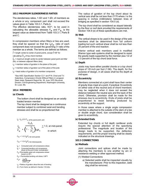
103.3 MAXIMUM SLENDERNESS RAT I O S<br />
The slenderness r<strong>at</strong>ios, 1.0l/r <strong>and</strong> 1.0l/ r, of members as<br />
a whole or any component part shall not exceed the<br />
values given in Table 103.3.1, Parts A .<br />
The effective slenderness r<strong>at</strong>io, Kl/r*, to be used in<br />
calcul<strong>at</strong>ing the allowable stresses F a <strong>and</strong> F' e , is the<br />
largest value as determined from Table 103.3.1, Parts B<br />
<strong>and</strong> C.<br />
In compression members when fillers or ties are used,<br />
they shall be spaced so th<strong>at</strong> the l s / r z , r<strong>at</strong>io of each<br />
component does not exceed the governing l/r r<strong>at</strong>io of the<br />
member as a whole. The terms are defined as follows:<br />
l = length center-to-center of panel points, except l=36" for<br />
calcul<strong>at</strong>ing l/r y of top chord member.<br />
l s = maximum length center-to-center between panel point <strong>and</strong> tiller<br />
(tie), or between adjacent fillers (ties).<br />
r x = member radius of gyr<strong>at</strong>ion in the plane of the joist.<br />
r y = member radius of gyr<strong>at</strong>ion out of the plane of the joist.<br />
r z = least radius of gyr<strong>at</strong>ion of a member component.<br />
*See AISC Specific<strong>at</strong>ion Section C2.1 <strong>and</strong> P.N. Chod <strong>and</strong> T. V.<br />
Galambos, Compression Chords Without Fillers in Longspan<br />
<strong>Steel</strong> <strong><strong>Joist</strong>s</strong>, Research Report No. 36, June 1975 Structural<br />
Division, Civil Engineering Department, Washington University,<br />
St. Louis, Mo.<br />
103.4 MEMBERS<br />
(a) Chord s<br />
The bottom chord shall be designed as an axially<br />
loaded tension member.<br />
The top chord shall be designed as a continuous<br />
member subject to combined axial <strong>and</strong> bending<br />
stresses <strong>and</strong> shall be so proportioned th<strong>at</strong><br />
f a + f b