Vulcraft Steel Joists and Joist Girders Catalog - Sites at Lafayette
Vulcraft Steel Joists and Joist Girders Catalog - Sites at Lafayette
Vulcraft Steel Joists and Joist Girders Catalog - Sites at Lafayette

Create successful ePaper yourself
Turn your PDF publications into a flip-book with our unique Google optimized e-Paper software.
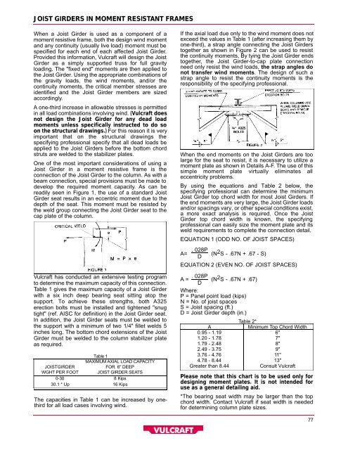
JOIST GIRDERS IN MOMENT RESISTANT FRAMES<br />
When a <strong>Joist</strong> Girder is used as a component of a<br />
moment resistive frame, both the design wind moment<br />
<strong>and</strong> any continuity (usually live load) moment must be<br />
specified for each end of each affected <strong>Joist</strong> Girder.<br />
Provided this inform<strong>at</strong>ion, <strong>Vulcraft</strong> will design the <strong>Joist</strong><br />
Girder as a simply supported truss for full gravity<br />
loading. The "fixed end" moments are then applied to<br />
the <strong>Joist</strong> Girder. Using the appropri<strong>at</strong>e combin<strong>at</strong>ions of<br />
the gravity loads, the wind moments, <strong>and</strong>/or the<br />
continuity moments, the critical member stresses are<br />
identified <strong>and</strong> the <strong>Joist</strong> Girder members are sized<br />
accordingly.<br />
A one-third increase in allowable stresses is permitted<br />
in all load combin<strong>at</strong>ions involving wind. (<strong>Vulcraft</strong> does<br />
not design the <strong>Joist</strong> Girder for any dead load<br />
moments unless specifically instructed to do so<br />
on the structural drawings.) For this reason it is very<br />
important th<strong>at</strong> on the structural drawings the<br />
specifying professional specify th<strong>at</strong> all dead loads be<br />
applied to the <strong>Joist</strong> <strong>Girders</strong> before the bottom chord<br />
struts are welded to the stabilizer pl<strong>at</strong>es.<br />
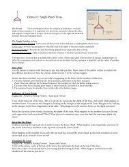
One of the most important consider<strong>at</strong>ions of using a<br />
<strong>Joist</strong> Girder in a moment resistive frame is the<br />
connection of the <strong>Joist</strong> Girder to the column. As with a<br />
beam connection, special provisions must be made to<br />
develop the required moment capacity. As can be<br />
readily seen in Figure 1, the use of a st<strong>and</strong>ard <strong>Joist</strong><br />
Girder se<strong>at</strong> results in an eccentric moment due to the<br />
depth of the se<strong>at</strong>. This moment must be resisted by<br />
the weld group connecting the <strong>Joist</strong> Girder se<strong>at</strong> to the<br />
cap pl<strong>at</strong>e of the column.<br />
<strong>Vulcraft</strong> has conducted an extensive testing program<br />
to determine the maximum capacity of this connection.<br />
Table 1 gives the maximum capacity of a <strong>Joist</strong> Girder<br />
with a six inch deep bearing se<strong>at</strong> sitting <strong>at</strong>op the<br />
support. To achieve these strengths, both A 3 2 5<br />
erection bolts must be installed <strong>and</strong> tightened "snug<br />
tight" (ref. AISC for definition) in the <strong>Joist</strong> Girder se<strong>at</strong>.<br />
In addition, the <strong>Joist</strong> Girder se<strong>at</strong>s must be welded to<br />
the support with a minimum of two 1/4" fillet welds 5<br />
inches long. The bottom chord extensions of the <strong>Joist</strong><br />
Girder must be welded to the column stabilizer pl<strong>at</strong>e<br />
as required.<br />
Table 1<br />
MAXIMUM A X I A LLOAD CAPA C I T Y<br />
J O I S TG I R D E R<br />
FOR 6" DEEP<br />
W G H TPER FOOT J O I S TGIRDER SEAT S<br />
0 - 30 8 K i p s<br />
30.1 * Up 16 Kips<br />
The capacities in Table 1 can be increased by onethird<br />
for all load cases involving wind.<br />
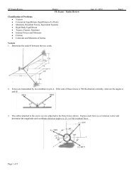
If the axial load due only to the wind moment does not<br />
exceed the values in Table 1 (after increasing them by<br />
one-third), a strap angle connecting the <strong>Joist</strong> <strong>Girders</strong><br />
together as shown in Figure 2 can be used to resist<br />
the continuity moments, By tying the <strong>Joist</strong> Girder ends<br />
t o g e t h e r, the <strong>Joist</strong> Girder-to-cap pl<strong>at</strong>e connection<br />
need only resist the wind loads, the strap angles do<br />
not transfer wind moments. The design of such a<br />
strap angle to resist the continuity moments is the<br />
responsibility of the specifying professional.<br />
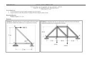
When the end moments on the <strong>Joist</strong> <strong>Girders</strong> are too<br />
large for the se<strong>at</strong> to resist, it is necessary to utilize a<br />
moment pl<strong>at</strong>e as shown in Details A-F. The use of this<br />
simple moment pl<strong>at</strong>e virtually elimin<strong>at</strong>es all<br />
eccentricity problems.<br />
By using the equ<strong>at</strong>ions <strong>and</strong> Table 2 below, the<br />
specifying professional can determine the minimum<br />
<strong>Joist</strong> Girder top chord width for most <strong>Joist</strong> <strong>Girders</strong>. If<br />
the end moments are very large, the <strong>Joist</strong> Girder loads<br />
<strong>and</strong>/or spacings vary, or other special conditions exist,<br />
a more exact analysis is required. Once the <strong>Joist</strong><br />
Girder top chord width is known, the specifying<br />
professional can easily size the moment pl<strong>at</strong>e <strong>and</strong> its<br />
weld requirements to complete the connection detail.<br />
EQUATION 1 (ODD NO. OF JOIST SPACES)<br />
. 028P<br />
A=<br />
D<br />
(N 2 S - .67N + .67 - S)<br />
EQUATION 2 (EVEN NO. OF JOIST SPACES)<br />
. 028P<br />
A = (N 2 S - .67N + .67)<br />
D<br />
Where:<br />
P = Panel point load (kips)<br />
N = No. of joist spaces<br />
S = <strong>Joist</strong> spacing (ft.)<br />
D = <strong>Joist</strong> Girder depth (in.)<br />
Table 2*<br />
Minimum Top Chord Width<br />
A<br />
0.95 - 1.19 6"<br />
1.20 - 1.78 7"<br />
1.79 - 2.48 8"<br />
2.49 - 3.75 9"<br />
3.76 - 4.76 11"<br />
4.78 - 8.44 13"<br />
Gre<strong>at</strong>er than 8.44<br />
Consult <strong>Vulcraft</strong><br />
Please note th<strong>at</strong> this chart is to be used only for<br />
designing moment pl<strong>at</strong>es. It is not intended for<br />
use as a general detailing aid.<br />
*The bearing se<strong>at</strong> width may be larger than the top<br />
chord width. Contact <strong>Vulcraft</strong> if se<strong>at</strong> width is needed<br />
for determining column pl<strong>at</strong>e sizes.<br />
7 7