Vulcraft Steel Joists and Joist Girders Catalog - Sites at Lafayette
Vulcraft Steel Joists and Joist Girders Catalog - Sites at Lafayette
Vulcraft Steel Joists and Joist Girders Catalog - Sites at Lafayette

You also want an ePaper? Increase the reach of your titles
YUMPU automatically turns print PDFs into web optimized ePapers that Google loves.
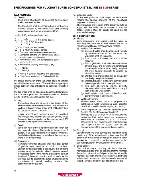
S P E C I F I C ATIONS FOR VULCRAFT SUPER LONGSPAN STEEL JOISTS S L H- S E R I E S<br />
203.4 MEMBERS<br />
( a ) C h o r d s<br />
The bottom chord shall be designed as an axially<br />
loaded tension member.<br />
The top chord shall be designed as a continuous<br />
member subject to combined axial <strong>and</strong> bending<br />
stresses <strong>and</strong> shall be so proportioned th<strong>at</strong><br />
The radius of gyr<strong>at</strong>ion of the top chord about its vertical<br />
axis shall be not less than l/170 where l is the spacing in<br />
inches between lines of bridging as specified in Section<br />
2 0 4 . 6 .<br />
The top chord shall be considered as stayed l<strong>at</strong>erally by<br />
the roof deck provided the requirements of Section<br />
204.10 (d) of these specific<strong>at</strong>ions are met.<br />
( b ) We b<br />
The vertical shears to be used in the design of the<br />
web members shall be determined from full uniform<br />
loading, but such vertical shear shall not be less than<br />
25 percent of the end reaction.<br />
Interior vertical web members used in modified<br />
Warren type web systems shall be designed to resist<br />
the gravity loads supported by the member plus 1 1/2<br />
percent of the top chord axial force.<br />
( c ) D e p t h<br />
<strong><strong>Joist</strong>s</strong> can have either a top chord pitch of l/4 inch per<br />
foot or parallel chords. The depth, for the purpose of<br />
design, in all cases shall be the depth <strong>at</strong> mid-span.<br />
Parallel chord joists must be installed with a minimum<br />
slope of l/4 inch per foot.<br />
(d ) E c c e n t r i c i t y<br />
Members connected <strong>at</strong> a joint shall have their center<br />
of gravity lines meet <strong>at</strong> a point, if practical.<br />
Eccentricity on either side of the neutral axis of chord<br />
members may be neglected when it does not exceed<br />
the distance between the neutral axis <strong>and</strong> the back of<br />
the chord. Otherwise, provision shall be made for the<br />
stresses due to eccentricity. Ends of joists shall be<br />
proportioned to resist bending produced by<br />
eccentricity <strong>at</strong> the support.<br />
( e ) Extended Ends<br />
Extended top chords or full depth cantilever ends<br />
require the special <strong>at</strong>tention of the specifying<br />
engineer or architect.<br />
The magnitude <strong>and</strong> loc<strong>at</strong>ion of the design loads to be<br />
supported, the deflection requirements, <strong>and</strong> the<br />
proper bracing shall be clearly indic<strong>at</strong>ed on the<br />
structural drawings.<br />
203.5 CONNECTIONS<br />
( a ) M e t h o d<br />
Joint connections <strong>and</strong> splices shall be made by<br />
<strong>at</strong>taching the members to one another by arc or<br />
resistance welding or other approved method.<br />
1 ) Welded Connections<br />
( a ) Selected welds shall be inspected visually<br />
by the manufacturer. Prior to this inspection,<br />
weld slag shall be removed.<br />
( b ) Cracks are not acceptable <strong>and</strong> shall be<br />
r e p a i r e d .<br />
(c) Thorough fusion shall exist between layers<br />
of weld metal <strong>and</strong> between weld metal <strong>and</strong><br />
base metal for the required design length of<br />
the weld; such fusion shall be verified by<br />
visual inspection.<br />
( d ) Unfilled weld cr<strong>at</strong>ers shall not be included in<br />
the design length of the weld.<br />
( e ) Undercut shall not exceed l/16 inch for welds<br />
oriented parallel to the principal stress.<br />
( f ) The sum of surface (piping) porosity<br />
diameters shall not exceed l/16 inch in any 1<br />
inch of design weld length.<br />
( g ) Weld sp<strong>at</strong>ter th<strong>at</strong> does not interfere with<br />
paint coverage is acceptable.<br />
2 ) Welding Program<br />
Manufacturers shall have a program for<br />
establishing weld procedures <strong>and</strong> oper<strong>at</strong>or<br />
qualific<strong>at</strong>ion <strong>and</strong> for weld sampling <strong>and</strong> testing.<br />
3 ) Weld inspection by Outside Agencies (See<br />
Section 204.14 of these specific<strong>at</strong>ions).<br />
The agency shall arrange for visual inspection to<br />
determine th<strong>at</strong> welds meet the acceptance<br />
st<strong>and</strong>ards of Section 203.5 a. 1) above.<br />
Ultrasonic X-Ray, <strong>and</strong> magnetic particle testing<br />
are inappropri<strong>at</strong>e for joists due to the<br />
configur<strong>at</strong>ions of the components <strong>and</strong> welds.<br />
( b ) S t r e n g t h<br />
Joint connections shall develop the maximum force<br />
due to any of the design loads, but not less than 50<br />
percent of the allowable strength of the member in<br />
tension or compression, whichever force is the<br />
controlling factor in the selection of the member.<br />
( c ) Shop Splices<br />
Shop splices may occur <strong>at</strong> any point in chord or web<br />
members. Splices shall be designed for the member<br />
force, but not less than 50 percent of the allowable<br />
member strength. Members containing a butt weld<br />
splice shall develop an ultim<strong>at</strong>e tensile force of <strong>at</strong><br />
least 57,000 psi times the full design area of the<br />
7 0