Vulcraft Steel Joists and Joist Girders Catalog - Sites at Lafayette
Vulcraft Steel Joists and Joist Girders Catalog - Sites at Lafayette
Vulcraft Steel Joists and Joist Girders Catalog - Sites at Lafayette

Create successful ePaper yourself
Turn your PDF publications into a flip-book with our unique Google optimized e-Paper software.
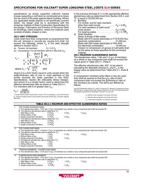
S P E C I F I C ATIONS FOR VULCRAFT SUPER LONGSPAN STEEL JOISTS S L H- S E R I E S<br />
specific<strong>at</strong>ions as simply supported uniformly loaded<br />
trusses supporting a roof deck so constructed as to brace<br />
the top chord of the joists against l<strong>at</strong>eral buckling. Where<br />
any applicable design fe<strong>at</strong>ure is not specifically covered<br />
herein, the design shall be in accordance with the<br />
American Institute of <strong>Steel</strong> Construction Specific<strong>at</strong>ion for<br />
the Design, Fabric<strong>at</strong>ion <strong>and</strong> Erection of Structural <strong>Steel</strong><br />
for Buildings, l<strong>at</strong>est adoption, where the m<strong>at</strong>erial used<br />
consists of pl<strong>at</strong>es, shapes or bars.<br />
203.2 UNIT STRESSES<br />
<strong><strong>Joist</strong>s</strong> shall have their components so proportioned th<strong>at</strong><br />
the unit stresses in pounds per square inch shall not<br />
exceed the following, where F y is the yield strength<br />
defined in Section 202.2:<br />
( a ) Tension: All members . . . . . . . . F t = 0.6 F y<br />
( b ) Compression: For all members with Kl /r less than C c :<br />
where Q is a form factor equal to unity except when the<br />
width-thickness r<strong>at</strong>io of one or more elements of the<br />
profile exceeds the limits specified in the AISC<br />
Specific<strong>at</strong>ions, Section B5 (Allowable Stress Design),<br />
<strong>and</strong> where K is a length factor used to determine the<br />
e ffective slenderness r<strong>at</strong>io as shown in Table 203.3.1.<br />
For rnembers with K l/r gre<strong>at</strong>er than C c ,:<br />
12 π<br />
F a =<br />
2 E<br />
23 (Kl / r ) 2<br />
l =Length center-to-center of panel points, except l= 36" for calcul<strong>at</strong>ing l /r y of top chord member<br />
l s = Maximum length center-to-center between panel point <strong>and</strong> filler (tie), or between adjacent<br />
fillers (ties).<br />
In the previous formulas K l /r is the appropri<strong>at</strong>e eff e c t i v e<br />
slenderness r<strong>at</strong>io as determined from Section 203.3, <strong>and</strong><br />
"E" is equal to 29,000,000 psi.<br />
c ) B e n d i n g :<br />
For chords, <strong>and</strong> for web members<br />
other than solid rounds . . . . . . . . . . . F b = 0.6F y<br />
For web members of solid round<br />
cross section . . . . . . . . . . . . . . . . . . . F b = 0.9F y<br />
For bearing pl<strong>at</strong>es . . . . . . . . . . . . . . . F b = 0.75F y<br />
d ) Weld Stresses:<br />
Shear <strong>at</strong> thro<strong>at</strong> of fillet welds:<br />
Made with E70 series electrodes or F7X-EXXX fluxelectrode<br />
combin<strong>at</strong>ions . . . . . . . . . . . 21,000 psi<br />
Made with E60 series electrodes or F6X-XXX<br />
flux-electrode combin<strong>at</strong>ion . . . . . . . . 18,000 psi<br />
Tension or compression on groove or butt welds shall<br />
be the same as those specified for the connected<br />
m a t e r i a l .<br />
203.3 MAXIMUM SLENDERNESS RAT I O S<br />
The slenderness r<strong>at</strong>ios, 1.0l/r <strong>and</strong> 1.0 l s / r, of members<br />
as a whole or any component part shall not exceed the<br />
values given in Table 203.3.1, Parts A .<br />
The effective slenderness r<strong>at</strong>io, Kl/r*, to be used in<br />
calcul<strong>at</strong>ing the allowable stresses F a <strong>and</strong> F' e , is the<br />
largest value as determined from Table 203.3.1, Parts B<br />
<strong>and</strong> C.<br />
In compression members when fillers or ties are used,<br />
they shall be spaced so th<strong>at</strong> the l s / r z r<strong>at</strong>io of each<br />
component does not exceed the governing l/r r<strong>at</strong>io of<br />
the members as a whole. The terms are defined as<br />
f o l l o w s .<br />
'See AISC Specific<strong>at</strong>ion Section C2.1 <strong>and</strong> P.N. Chod <strong>and</strong> T. V. Galambos, Compression Chords<br />
Without Fillers in Longspan <strong>Steel</strong> <strong><strong>Joist</strong>s</strong>, Research Report No. 36, June 1975 Structural Division,<br />
Civil Engineering Department. Washington University, St. Louis, MO.<br />
r x = Member radius of gyr<strong>at</strong>ion in the plane of the joist.<br />
r y = Member radius of gyr<strong>at</strong>ion out of plane of the joist.<br />
r z = Least radius of gyr<strong>at</strong>ion of a member component.<br />
I .<br />
I I .<br />
I l l .<br />
I V.<br />
TABLE 203.3.1 MAXIMUM AND EFFECTIVE SLENDERNESS RAT I O S<br />
TO P CHORD INTERIOR PA N E L<br />
A. The slenderness r<strong>at</strong>ios, 1.0 l/r <strong>and</strong> 1.0 l s / r, of members as a whole or any component part shall not exceed 90.<br />
B. The effective slenderness r<strong>at</strong>io to determine "F a "<br />
1. With fillers or ties 0.75 l/ r x 1.0 l/ r y 1.0 l s / r z<br />
2. Without fillers or ties 0.75 l/ r z<br />
3. Single component members 0.75 l/ r x 1.0 l/ r y<br />
C. The effective slenderness r<strong>at</strong>io to determine "F' e "<br />
1. With fillers or ties 0.75 l/ r x<br />
2. Without fillers or ties 0.75 l/ r x<br />
3. Single component members 0.75 l/ r x<br />
TO P CHORD END PA N E L<br />
A. The slenderness r<strong>at</strong>ios, 1.0 l/r<strong>and</strong> 1.0 l s / r, of members as a whole or any component part shall not exceed 120.<br />
B. The effective slenderness r<strong>at</strong>io to determine "F a "<br />
1. With fillers or ties 1.0 l/ r x 1.0 l/ r y 1.0 l s / r z<br />
2. Without fillers or ties 1.0 l/ r z<br />
3. Single component members 1.0 l/ r x 1.0 l/ r y<br />
C.The effective slenderness r<strong>at</strong>io to determine "F' e "<br />
1. With fillers or ties 1.0 l/ r x<br />
2. Without fillers or ties 1.0 l/ r x<br />
3. Single component members 1.0 l/ r x<br />
TENSION MEMBERS - CHORDS AND WEBS<br />
A. The slenderness r<strong>at</strong>ios, 1.0 l/r <strong>and</strong> 1.0 l s / r, of members as a whole or any component p<strong>at</strong>t shall not exceed 240.<br />
COMPRESSION WEB MEMBERS<br />
A. The slenderness r<strong>at</strong>ios, 1.0 l/r <strong>and</strong> 1.0 l s / r, of members as a whole or any component part shall not exceed 200.<br />
B. The effective slenderness r<strong>at</strong>io to determine "F a '<br />
1. With fillers or ties 0.75 l/ r x 1.0 l/ r y 1.0 l s / r z<br />
2. Without fillers or ties 1.0 l/ r z<br />
3. Single component members 0.75 l/ r x 1.0 l/ r y<br />
6 9