Vulcraft Steel Joists and Joist Girders Catalog - Sites at Lafayette
Vulcraft Steel Joists and Joist Girders Catalog - Sites at Lafayette
Vulcraft Steel Joists and Joist Girders Catalog - Sites at Lafayette

Create successful ePaper yourself
Turn your PDF publications into a flip-book with our unique Google optimized e-Paper software.
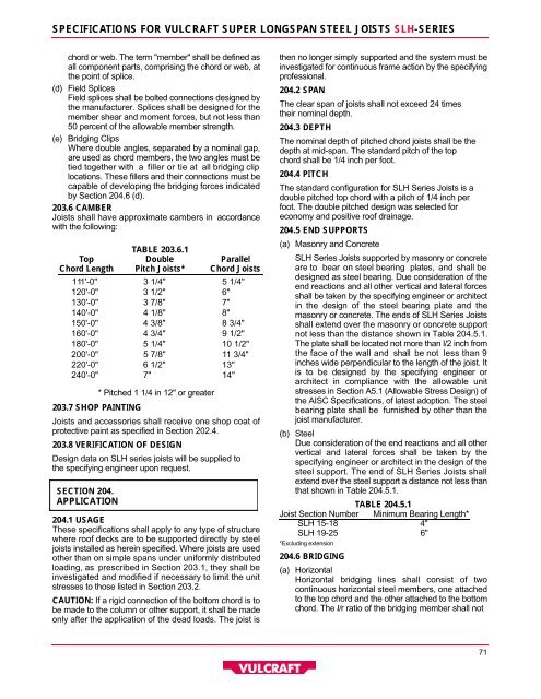
S P E C I F I C ATIONS FOR VULCRAFT SUPER LONGSPAN STEEL JOISTS S L H- S E R I E S<br />
chord or web. The term "member" shall be defined as<br />
all component parts, comprising the chord or web, <strong>at</strong><br />
the point of splice.<br />
( d ) Field Splices<br />
Field splices shall be bolted connections designed by<br />
the manufacturer. Splices shall be designed for the<br />
member shear <strong>and</strong> moment forces, but not less than<br />
50 percent of the allowable member strength.<br />
( e ) Bridging Clips<br />
Where double angles, separ<strong>at</strong>ed by a nominal gap,<br />
are used as chord members, the two angles must be<br />
tied together with a filler or tie <strong>at</strong> all bridging clip<br />
loc<strong>at</strong>ions. These fillers <strong>and</strong> their connections must be<br />
capable of developing the bridging forces indic<strong>at</strong>ed<br />
by Section 204.6 (d).<br />
203.6 CAMBER<br />
<strong><strong>Joist</strong>s</strong> shall have approxim<strong>at</strong>e cambers in accordance<br />
with the following:<br />
TABLE 203.6.1<br />
To p D o u b l e P a r a l l e l<br />
C h o rd Length Pitch <strong><strong>Joist</strong>s</strong>* C h o rd <strong><strong>Joist</strong>s</strong><br />
111'-0"<br />
120'-0"<br />
130'-0"<br />
140'-0"<br />
150'-0"<br />
160'-0"<br />
180'-0"<br />
200'-0"<br />
220'-0"<br />
240'-0"<br />
203.7 SHOP PA I N T I N G<br />
* Pitched 1 1/4 in 12" or gre<strong>at</strong>er<br />
<strong><strong>Joist</strong>s</strong> <strong>and</strong> accessories shall receive one shop co<strong>at</strong> of<br />
protective paint as specified in Section 202.4.<br />
203.8 VERIFICATION OF DESIGN<br />
Design d<strong>at</strong>a on SLH series joists will be supplied to<br />
the specifying engineer upon request.<br />
SECTION 204.<br />
A P P L I C AT I O N<br />
3 1/4"<br />
3 1/2"<br />
3 7/8"<br />
4 1/8"<br />
4 3/8"<br />
4 3/4"<br />
5 1/4"<br />
5 7/8"<br />
6 1/2"<br />
7"<br />
5 1/4"<br />
6"<br />
7"<br />
8"<br />
8 3/4"<br />
9 1/2"<br />
10 1/2"<br />
11 3/4"<br />
13"<br />
14"<br />
204.1 USAGE<br />
These specific<strong>at</strong>ions shall apply to any type of structure<br />
where roof decks are to be supported directly by steel<br />
joists installed as herein specified. Where joists are used<br />
other than on simple spans under uniformly distributed<br />
loading, as prescribed in Section 203.1, they shall be<br />
investig<strong>at</strong>ed <strong>and</strong> modified if necessary to limit the unit<br />
stresses to those listed in Section 203.2.<br />
C A U T I O N :If a rigid connection of the bottom chord is to<br />
be made to the column or other support, it shall be made<br />
only after the applic<strong>at</strong>ion of the dead loads. The joist is<br />
then no longer simply supported <strong>and</strong> the system must be<br />
investig<strong>at</strong>ed for continuous frame action by the specifying<br />
p r o f e s s i o n a l .<br />
204.2 SPA N<br />
The clear span of joists shall not exceed 24 times<br />
their nominal depth.<br />
204.3 DEPTH<br />
The nominal depth of pitched chord joists shall be the<br />
depth <strong>at</strong> mid-span. The st<strong>and</strong>ard pitch of the top<br />
chord shall be 1/4 inch per foot.<br />
204.4 PITCH<br />
The st<strong>and</strong>ard configur<strong>at</strong>ion for SLH Series <strong><strong>Joist</strong>s</strong> is a<br />
double pitched top chord with a pitch of 1/4 inch per<br />
foot. The double pitched design was selected for<br />
economy <strong>and</strong> positive roof drainage.<br />
204.5 END SUPPORT S<br />
( a ) Masonry <strong>and</strong> Concrete<br />
SLH Series <strong><strong>Joist</strong>s</strong> supported by masonry or concrete<br />
are to bear on steel bearing pl<strong>at</strong>es, <strong>and</strong> shall be<br />
designed as steel bearing. Due consider<strong>at</strong>ion of the<br />
end reactions <strong>and</strong> all other vertical <strong>and</strong> l<strong>at</strong>eral forces<br />
shall be taken by the specifying engineer or architect<br />
in the design of the steel bearing pl<strong>at</strong>e <strong>and</strong> the<br />
masonry or concrete. The ends of SLH Series <strong><strong>Joist</strong>s</strong><br />
shall extend over the masonry or concrete support<br />
not less than the distance shown in Table 204.5.1.<br />
The pl<strong>at</strong>e shall be loc<strong>at</strong>ed not more than l/2 inch from<br />
the face of the wall <strong>and</strong> shall be not less than 9<br />
inches wide perpendicular to the length of the joist. It<br />
is to be designed by the specifying engineer or<br />
architect in compliance with the allowable unit<br />
stresses in Section A5.1 (Allowable Stress Design) of<br />
the AISC Specific<strong>at</strong>ions, of l<strong>at</strong>est adoption. The steel<br />
bearing pl<strong>at</strong>e shall be furnished by other than the<br />
joist manufacturer.<br />
( b ) S t e e l<br />
Due consider<strong>at</strong>ion of the end reactions <strong>and</strong> all other<br />
vertical <strong>and</strong> l<strong>at</strong>eral forces shall be taken by the<br />
specifying engineer or architect in the design of the<br />
steel support. The end of SLH Series <strong><strong>Joist</strong>s</strong> shall<br />
extend over the steel support a distance not less than<br />
th<strong>at</strong> shown in Table 204.5.1.<br />
TABLE 204.5.1<br />
<strong>Joist</strong> Section Number Minimum Bearing Length*<br />
SLH 15-18 4 "<br />
SLH 19-25 6 "<br />
*Excluding extension<br />
204.6 BRIDGING<br />
( a ) H o r i z o n t a l<br />
Horizontal bridging lines shall consist of two<br />
continuous horizontal steel members, one <strong>at</strong>tached<br />
to the top chord <strong>and</strong> the other <strong>at</strong>tached to the bottom<br />
chord. The l /r r<strong>at</strong>io of the bridging member shall not<br />
7 1