1642-VLZ3 16-Channel Mic/Line Mixer Owner's Manual
1642-VLZ3 16-Channel Mic/Line Mixer Owner's Manual
1642-VLZ3 16-Channel Mic/Line Mixer Owner's Manual

Create successful ePaper yourself
Turn your PDF publications into a flip-book with our unique Google optimized e-Paper software.
3<br />
Unless you know for certain it is safe to do<br />
so, never plug single-ended (un bal anced)<br />
microphones, instruments, ribbon mics, or<br />
electronic devices into the MIC [1] input jacks if the<br />
phantom power is on.<br />
2. LINE INPUTS<br />
These 1/4" jacks share circuitry (but not phantom<br />
power) with the mic preamps. You can use these inputs<br />
for virtually any signal you’ll come across, from instrument<br />
levels as low as –50 dB to operating levels of –10<br />
dBV to +4 dBu, as there is 45 dB of gain available via the<br />
GAIN [3] knob. Note that channels 1-8 line inputs are<br />
intially attenuated by 15 dB.<br />
Always be sure to perform the Level-Setting Procedure<br />
(page 3) when you connect a new input.<br />
To learn how signals are routed from these inputs,<br />
see the details lovingly described in the <strong>Channel</strong> Strip<br />
section.<br />
To connect balanced lines to these inputs, use a 1/4"<br />
tip-ring-sleeve (TRS) plug, the type found on some<br />
stereo headphones:<br />
Tip = positive (+ or hot)<br />
Ring = negative (– or cold)<br />
Sleeve = shield or ground<br />
To connect unbalanced lines to these inputs, use a<br />
1/4" mono (TS) phone plug or standard instrument<br />
cable:<br />
Tip = signal (+)<br />
Sleeve = ground<br />
3. GAIN<br />
These controls are not in the patchbay, but<br />
they are the top row of knobs in the channel<br />
strip section. (They are so vitally linked with<br />
the inputs, this seemed like a good place to<br />
describe them.)<br />
Every time you plug something into a<br />
MIC [1] or LINE [2] input jack, you should<br />
perform the Level-Setting Procedure, and that<br />
procedure is basically “how to use the GAIN<br />
knob.”<br />
GAIN adjusts the input sensitivity of the<br />
MIC and LINE inputs. This allows signals<br />
from the outside world to be adjusted to<br />
optimal internal operating levels.<br />
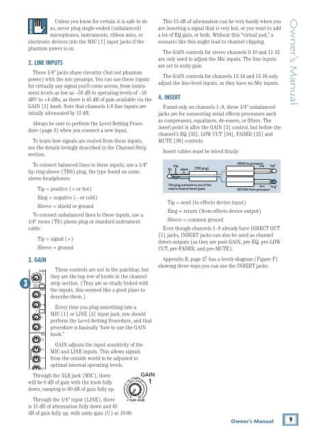
Through the XLR jack (MIC), there<br />
will be 0 dB of gain with the knob fully<br />
down, ramping to 60 dB of gain fully up.<br />
Through the 1/4" input (LINE), there<br />
is 15 dB of attenuation fully down and 45<br />
dB of gain fully up, with unity gain (U) at 10:00.<br />
This 15 dB of attenuation can be very handy when you<br />
are inserting a signal that is very hot, or you want to add<br />
a lot of EQ gain, or both. Without this “virtual pad,” a<br />
scenario like this might lead to channel clipping.<br />
The GAIN controls for stereo channels 9-10 and 11-12<br />
are only used to adjust the <strong>Mic</strong> inputs. The line inputs<br />
are set to unity gain.<br />
The GAIN controls for channels 13-14 and 15-<strong>16</strong> only<br />
adjust the line-level inputs, as they have no <strong>Mic</strong> inputs.<br />
4. INSERT<br />
Found only on channels 1–8, these 1/4" unbalanced<br />
jacks are for connecting serial effects processors such<br />
as compressors, equalizers, de-essers, or filters. The<br />
insert point is after the GAIN [3] control, but before the<br />
channel’s EQ [32], LOW CUT [34], FADER [25] and<br />
MUTE [30] controls.<br />
Insert cables must be wired thusly:<br />
tip ring sleeve<br />
(TRS plug)<br />
This plug connects to one of the<br />
mixer’s <strong>Channel</strong> Insert jacks.<br />
SEND to processor<br />
Tip = send (to effects device input)<br />
Ring = return (from effects device output)<br />
Sleeve = common ground<br />
Even though channels 1–8 already have DIRECT OUT<br />
[5] jacks, INSERT jacks can also be used as channel<br />
direct outputs (as they are post-GAIN, pre-EQ, pre-LOW<br />
CUT, pre-FADER, and pre-MUTE).<br />
“tip”<br />
“ring”<br />
RETURN from processor<br />
Appendix B, page 27 has a lovely diagram (Figure F)<br />
showing three ways you can use the INSERT jacks.<br />
Owner’s <strong>Manual</strong><br />
Owner’s <strong>Manual</strong><br />
9