POWER UP A WINNER - Plant Services
POWER UP A WINNER - Plant Services
POWER UP A WINNER - Plant Services

Create successful ePaper yourself
Turn your PDF publications into a flip-book with our unique Google optimized e-Paper software.
Reliability / Piping<br />
rations that can reconcile these conflicting Pressure counts<br />
criteria for more sustainable piping systems.<br />
Industry has made great strides in<br />
reducing the number of leaks from<br />
flanged joints, and some plants have even<br />
eliminated them. Because reliable piping<br />
system performance, including pumps,<br />
valves and other equipment, is critical to<br />
plant sustainability both operationally<br />
and environmentally, it’s vital to pay careful<br />
attention to these flanged joints and<br />
the gaskets that keep them from leaking.<br />
Before replacing a leaking gasket, make<br />
sure you’ve identified the root cause of the<br />
leak. A good place to start is to verify that<br />
the proper gasket was installed in the first place based on the<br />
operating parameters of the system, notably temperature, media<br />
and pressure. The first consideration should be temperature<br />
because it can eliminate many unsuitable gasket materials from<br />
consideration. Next, look at the media’s chemical compatibility<br />
with the gasket, including any secondary media to which the<br />
gasket might be exposed, such as fluids that are intermittently<br />
present during chemical or steam/hot-water flushing. Then<br />
consider pressure. Most systems operate at relatively consistent<br />
pressure, but it’s important to take into account severe spikes or<br />
surges that might occur.<br />
However, selecting the right gasket requires an understanding<br />
of the application that goes beyond these criteria.<br />
Flanged joints rarely leak because chemicals attacked the<br />
gasket. Most people understand that gasket materials must<br />
be compatible with system media. Likewise, it’s rare to find a<br />
piping system that exceeds a gasket’s maximum pressure or<br />
temperature ratings.<br />
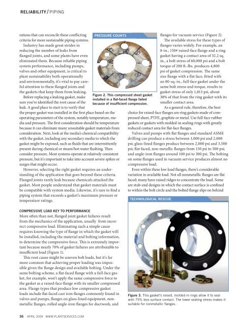
Figure 2. This compressed sheet gasket<br />
installed in a flat-faced flange failed<br />
because of insufficient compression.<br />
flanges for vacuum service (Figure 2).<br />
The available stress for these types of<br />
flanges varies widely. For example, an<br />
8-in., 150# raised-face flange and a ring<br />
gasket having a contact area of 32.2 sq.<br />
in., a bolt stress of 60,000 psi and a bolt<br />
torque of 200 ft.-lbs. produces 4,800<br />
psi of gasket compression. The same<br />
size flange with a flat face, fitted with<br />
an 80-sq.-in., full-face gasket under the<br />
same bolt stress and torque, results in<br />
gasket stress of only 1,813 psi, about<br />
38% of that from the ring gasket with its<br />
smaller contact area.<br />
As a general rule, therefore, the best<br />
choice for raised-face flanges are ring gaskets made of compressed<br />
sheet, PTFE, graphite or metal. Use full-face rubber<br />
gaskets or gaskets with molded-in sealing rings with greatly<br />
reduced contact area for flat-face flanges.<br />
Valves and pumps with flat flanges and standard ASME<br />
drilling can produce a stress between 1,000 psi and 2,000<br />
psi; glass-lined flanges produce between 2,000 psi and 3,500<br />
psi; flat-faced, non-metallic flanges from 150 psi to 500 psi;<br />
and angle-iron flanges around 100 psi to 300 psi. The bolting<br />
on some flanges used in vacuum service produces almost no<br />
compressive load.<br />
Even within these low-load flanges, there’s considerable<br />
variation in available load. Not all nonmetallic flanges are flat<br />
faced; many have raised ridges to concentrate the load. Some<br />
are stub-end designs in which the contact surface is confined<br />
to within the bolt circle and the bolted flange slips on behind<br />
Technological rescue<br />
Compressive load key to performance<br />
More often than not, flanged joint gasket failures result<br />
from the mechanics of the application, usually from incorrect<br />
compressive load. Eliminating such a simple cause<br />
requires knowing the type of flange in which the gasket will<br />
be installed, including the material and bolting information,<br />
to determine the compressive force. This is extremely important<br />
because nearly 70% of gasket failures are attributable to<br />
insufficient load (Figure 1).<br />
This root cause might be uneven bolt loads, but it’s far<br />
more common that achieving proper loading was impossible<br />
given the flange design and available bolting. Under the<br />
same bolting scheme, a flat-faced flange with a full-face gasket,<br />
for example, won’t apply the same compressive force to<br />
the gasket as a raised-face flange with its smaller compressed<br />
area. Flange types that produce low compressive gasket<br />
loads include flat-faced cast iron flanges commonly found in<br />
valves and pumps, flanges on glass-lined equipment, nonmetallic<br />
flanges, rolled angle-iron flanges for ductwork, and<br />
Figure 3. This gasket’s raised, molded-in rings allow it to seal<br />
with 75% less surface contact. The lower seating stress makes it<br />
suitable for nonmetallic flanges.<br />
36 APRIL 2009 www.PLANTSERVICES.com