wireless monitoring system of gas detector - Faculty of Electrical ...
wireless monitoring system of gas detector - Faculty of Electrical ...
wireless monitoring system of gas detector - Faculty of Electrical ...

Create successful ePaper yourself
Turn your PDF publications into a flip-book with our unique Google optimized e-Paper software.
21<br />
DC power<br />
supply<br />
Arduino<br />
Board<br />
Alarm<br />
Indicator<br />
Gas Sensor<br />
LABVIEW<br />
(GUI)<br />
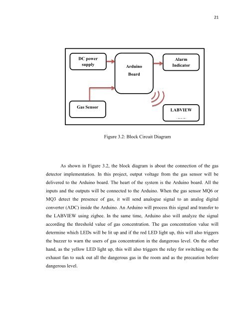
Figure 3.2: Block Circuit Diagram<br />
As shown in Figure 3.2, the block diagram is about the connection <strong>of</strong> the <strong>gas</strong><br />
<strong>detector</strong> implementation. In this project, output voltage from the <strong>gas</strong> sensor will be<br />
delivered to the Arduino board. The heart <strong>of</strong> the <strong>system</strong> is the Arduino board. All the<br />
inputs and the outputs will be connected to the Arduino. When the <strong>gas</strong> sensor MQ6 or<br />
MQ3 detect the presence <strong>of</strong> <strong>gas</strong>, it will send analogue signal to an analog digital<br />
converter (ADC) inside the Arduino. An Arduino will process this signal and transfer to<br />
the LABVIEW using zigbee. In the same time, Arduino also will analyze the signal<br />
according the threshold value <strong>of</strong> <strong>gas</strong> concentration. The <strong>gas</strong> concentration value will<br />
determine which LEDs will be lit up and if the red LED light up, this will also triggers<br />
the buzzer to warn the users <strong>of</strong> <strong>gas</strong> concentration in the dangerous level. On the other<br />
hand, as the yellow LED light up, this will also triggers the relay for switching on the<br />
exhaust fan to suck out all the dangerous <strong>gas</strong> in the room and as the precaution before<br />
dangerous level.