wireless monitoring system of gas detector - Faculty of Electrical ...
wireless monitoring system of gas detector - Faculty of Electrical ...
wireless monitoring system of gas detector - Faculty of Electrical ...

Create successful ePaper yourself
Turn your PDF publications into a flip-book with our unique Google optimized e-Paper software.
27<br />
Figure 3.8 show the output circuit diagram which act as the alarm <strong>system</strong> to the<br />
<strong>system</strong>. Red LED and buzzer are connected in the same pin from the Arduino, 13. Same<br />
as the yellow LED and exhaust fan at the pin 11. At the same time, pin 11 includes the<br />
relay circuit act as a switch tothe exhaust fan. All the LEDs are covered with a light<br />
transparents casing in previously shown in Figure 3.3 to give visibility to the brightness<br />
when the LEDs light up. The output for pin 12 from Arduino is green LED only.<br />
9V<br />
5V<br />
3 4<br />
normally open<br />
2<br />
1<br />
normally closed<br />
5<br />
RELAY<br />
R<br />
11 Transistor<br />
exzos<br />
fan<br />
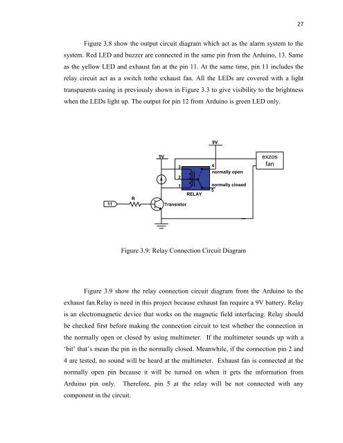
Figure 3.9: Relay Connection Circuit Diagram<br />
Figure 3.9 show the relay connection circuit diagram from the Arduino to the<br />
exhaust fan.Relay is need in this project because exhaust fan require a 9V battery. Relay<br />
is an electromagnetic device that works on the magnetic field interfacing. Relay should<br />
be checked first before making the connection circuit to test whether the connection in<br />
the normally open or closed by using multimeter. If the multimeter sounds up with a<br />
„bit‟ that‟s mean the pin in the normally closed. Meanwhile, if the connection pin 2 and<br />
4 are tested, no sound will be heard at the multimeter. Exhaust fan is connected at the<br />
normally open pin because it will be turned on when it gets the information from<br />
Arduino pin only. Therefore, pin 5 at the relay will be not connected with any<br />
component in the circuit.