wireless monitoring system of gas detector - Faculty of Electrical ...
wireless monitoring system of gas detector - Faculty of Electrical ...
wireless monitoring system of gas detector - Faculty of Electrical ...

You also want an ePaper? Increase the reach of your titles
YUMPU automatically turns print PDFs into web optimized ePapers that Google loves.
43<br />
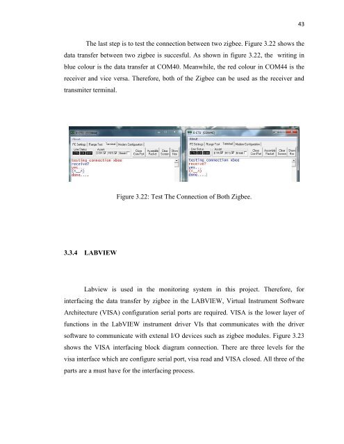
The last step is to test the connection between two zigbee. Figure 3.22 shows the<br />
data transfer between two zigbee is succesful. As shown in figure 3.22, the writing in<br />
blue colour is the data transfer at COM40. Meanwhile, the red colour in COM44 is the<br />
receiver and vice versa. Therefore, both <strong>of</strong> the Zigbee can be used as the receiver and<br />
transmiter terminal.<br />
Figure 3.22: Test The Connection <strong>of</strong> Both Zigbee.<br />
3.3.4 LABVIEW<br />
Labview is used in the <strong>monitoring</strong> <strong>system</strong> in this project. Therefore, for<br />
interfacing the data transfer by zigbee in the LABVIEW, Virtual Instrument S<strong>of</strong>tware<br />
Architecture (VISA) configuration serial ports are required. VISA is the lower layer <strong>of</strong><br />
functions in the LabVIEW instrument driver VIs that communicates with the driver<br />
s<strong>of</strong>tware to communicate with extenal I/O devices such as zigbee modules. Figure 3.23<br />
shows the VISA interfacing block diagram connection. There are three levels for the<br />
visa interface which are configure serial port, visa read and VISA closed. All three <strong>of</strong> the<br />
parts are a must have for the interfacing process.