Surgivet® V1030 Hand-Held Pulse Oximeter
Surgivet® V1030 Hand-Held Pulse Oximeter
Surgivet® V1030 Hand-Held Pulse Oximeter

You also want an ePaper? Increase the reach of your titles
YUMPU automatically turns print PDFs into web optimized ePapers that Google loves.
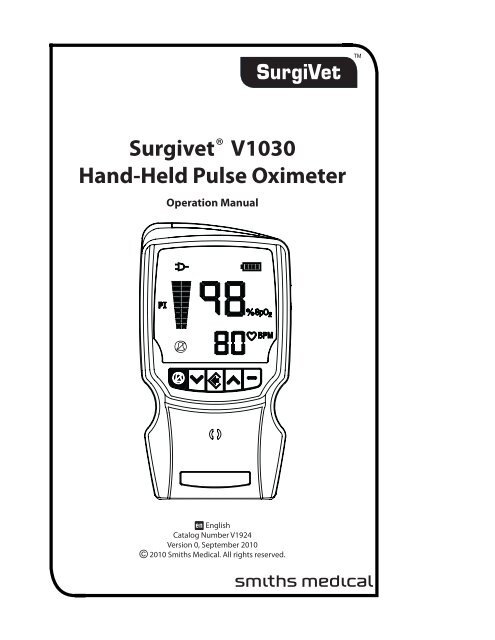
Surgivet® <strong>V1030</strong><br />
<strong>Hand</strong>-<strong>Held</strong> <strong>Pulse</strong> <strong>Oximeter</strong><br />
Operation Manual<br />
B<br />
B<br />
- English<br />
Catalog Number V1924<br />
Version 0, September 2010<br />
© 2010 Smiths Medical. All rights reserved.<br />
s
Table of Contents<br />
Table of Contents<br />
Warranty and Service Information......................................................................v<br />
Proprietary Notice....................................................................................................................................................... v<br />
Warranty......................................................................................................................................................................... v<br />
Limited Warranty................................................................................................................................................ v<br />
Loaner Device (Domestic Sales Only)......................................................................................................... v<br />
Disclaimer of Warranties.................................................................................................................................. v<br />
Conditions of Warranty.................................................................................................................................... v<br />
Limitation of Remedies................................................................................................................................... vi<br />
Warranty Procedure.................................................................................................................................................. vi<br />
CE Notice....................................................................................................................................................................... vi<br />
Chapter 1: Introduction................................................................................... 1-1<br />
About the Manual................................................................................................................................................... 1-1<br />
Definition of Symbols............................................................................................................................................ 1-1<br />
Warnings.................................................................................................................................................................... 1-3<br />
Cautions...................................................................................................................................................................... 1-7<br />
Notes............................................................................................................................................................................ 1-8<br />
Chapter 2: Intended Use and Monitor Features.............................................. 2-1<br />
Intended Use............................................................................................................................................................ 2-1<br />
Monitor Features..................................................................................................................................................... 2-1<br />
Theory of Operation............................................................................................................................................... 2-1<br />
<strong>Pulse</strong> Amplitude Index.......................................................................................................................................... 2-2<br />
<strong>Oximeter</strong>..................................................................................................................................................................... 2-3<br />
Chapter 3: Controls and Features.................................................................... 3-1<br />
Monitor Front View ................................................................................................................................................ 3-1<br />
Front Display............................................................................................................................................................. 3-2<br />
Monitor Operating Keys....................................................................................................................................... 3-3<br />
Monitor Back and Bottom Panels...................................................................................................................... 3-4<br />
Chapter 4: Operating Instructions................................................................... 4-1<br />
Unpacking the Monitor........................................................................................................................................ 4-1<br />
Powering the <strong>Oximeter</strong>......................................................................................................................................... 4-1<br />
Installing the Batteries.......................................................................................................................................... 4-3<br />
External Power ........................................................................................................................................................ 4-4<br />
AC Power.................................................................................................................................................................... 4-5<br />
Turning On the Monitor........................................................................................................................................ 4-5<br />
Checking the Monitor’s Performance.............................................................................................................. 4-6<br />
Attaching the Sensor to the Patient................................................................................................................. 4-7<br />
Choosing the Sensor.............................................................................................................................................. 4-7<br />
<strong>Pulse</strong> <strong>Oximeter</strong> Sensors........................................................................................................................................ 4-8<br />
Reflectance Sensors............................................................................................................................................... 4-8<br />
Veterinary <strong>V1030</strong> <strong>Hand</strong>-<strong>Held</strong> <strong>Pulse</strong> <strong>Oximeter</strong> Operation Manual<br />
i
Table of Contents<br />
<strong>Pulse</strong> <strong>Oximeter</strong> Sensor Application Tips ........................................................................................................ 4-9<br />
Testing Sensor Function....................................................................................................................................... 4-9<br />
Primary Applications for Sensors...................................................................................................................... 4-9<br />
Universal ‘Y’ Sensor and Mini Clip Sensor.............................................................................................. 4-9<br />
C Sensor...........................................................................................................................................................4-10<br />
Reflectance Sensor.......................................................................................................................................4-10<br />
Limitations...............................................................................................................................................................4-10<br />
Cleaning or Disinfecting the Sensors.............................................................................................................4-10<br />
Checking the Sensor and Oximetry Cable...................................................................................................4-10<br />
<strong>Pulse</strong> Amplitude Index........................................................................................................................................4-11<br />
Chapter 5: Changing the Monitor’s Settings................................................... 5-1<br />
Changing the <strong>Pulse</strong> Beep Volume..................................................................................................................... 5-1<br />
Setup Menu............................................................................................................................................................... 5-1<br />
SpO 2 and <strong>Pulse</strong> Rate Averaging......................................................................................................................... 5-2<br />
High Sensitivity Mode........................................................................................................................................... 5-2<br />
Display Brightness.................................................................................................................................................. 5-3<br />
Clock/ Calendar........................................................................................................................................................ 5-3<br />
Year, Month, Day............................................................................................................................................. 5-3<br />
Hours, Minutes................................................................................................................................................ 5-4<br />
Restore Alarm Defaults......................................................................................................................................... 5-5<br />
Menu............................................................................................................................................................................ 5-5<br />
Trend Interval........................................................................................................................................................... 5-6<br />
Language................................................................................................................................................................... 5-6<br />
Factory Defaults....................................................................................................................................................... 5-7<br />
Chapter 6: Alarms.............................................................................................. 6-1<br />
Alarm Priorities......................................................................................................................................................... 6-1<br />
Silencing Alarm Tones .......................................................................................................................................... 6-1<br />
High Priority Alarms............................................................................................................................................... 6-2<br />
Medium Priority Alarms........................................................................................................................................ 6-2<br />
Low Battery....................................................................................................................................................... 6-3<br />
Low Priority Alarms................................................................................................................................................ 6-3<br />
Alarm Summary....................................................................................................................................................... 6-4<br />
Alarm Menu............................................................................................................................................................... 6-4<br />
Alarm Limit Defaults by Patient Type...................................................................................................... 6-4<br />
Changing the Alarm Limits ........................................................................................................................ 6-5<br />
Restoring Default Alarm Limits................................................................................................................. 6-6<br />
ii<br />
Veterinary <strong>V1030</strong> <strong>Hand</strong>-<strong>Held</strong> <strong>Pulse</strong> <strong>Oximeter</strong> Operation Manual
Table of Contents<br />
Chapter 7: Patient Record Number and Trend Data....................................... 7-1<br />
Description................................................................................................................................................................ 7-1<br />
Incrementing the Patient Record Number ................................................................................................... 7-1<br />
Memory Capacity.................................................................................................................................................... 7-1<br />
Adjusting the Trend Storage Interval............................................................................................................... 7-1<br />
Clearing Trend Data................................................................................................................................................ 7-1<br />
Trend Data Output.................................................................................................................................................. 7-1<br />
Chapter 8: Optional Docking Station and Printer.......................................... 8-1<br />
Description................................................................................................................................................................ 8-1<br />
Docking Station....................................................................................................................................................... 8-2<br />
Powering the Docking Station.................................................................................................................. 8-2<br />
WW1090 Lithium-Ion (Li+) Rechargeable Battery Pack.................................................................... 8-3<br />
Installing the <strong>Oximeter</strong> to the Dock........................................................................................................ 8-3<br />
Printer.......................................................................................................................................................................... 8-4<br />
Attaching the Printer..................................................................................................................................... 8-5<br />
Loading Paper.................................................................................................................................................. 8-6<br />
Choosing the Print Mode ........................................................................................................................... 8-7<br />
Trend Data Condition Flags................................................................................................................................. 8-8<br />
Chapter 9: PC Communication Setup.............................................................. 9-1<br />
Description................................................................................................................................................................ 9-1<br />
Sensor / RS232 Port................................................................................................................................................ 9-2<br />
How to Set Up Equipment.......................................................................................................................... 9-2<br />
Output Format................................................................................................................................................. 9-3<br />
Chapter 10: Maintenance............................................................................... 10-1<br />
Routine Maintenance..........................................................................................................................................10-1<br />
Cleaning and Disinfecting.................................................................................................................................10-1<br />
Storage......................................................................................................................................................................10-2<br />
Chapter 11: Troubleshooting......................................................................... 11-1<br />
Correcting an Alert Condition..........................................................................................................................11-1<br />
Power.........................................................................................................................................................................11-2<br />
Sensor........................................................................................................................................................................11-3<br />
Printer and Data Communication...................................................................................................................11-4<br />
Other..........................................................................................................................................................................11-5<br />
Chapter 12: Optional Supplies and Accessories........................................... 12-1<br />
Ordering Information..........................................................................................................................................12-1<br />
Chapter 13: Specifications.............................................................................. 13-1<br />
Displays.....................................................................................................................................................................13-1<br />
Indicators.................................................................................................................................................................13-1<br />
Keys/User Controls...............................................................................................................................................13-1<br />
SpO 2 ...........................................................................................................................................................................13-2<br />
Veterinary <strong>V1030</strong> <strong>Hand</strong>-<strong>Held</strong> <strong>Pulse</strong> <strong>Oximeter</strong> Operation Manual<br />
iii
Table of Contents<br />
<strong>Pulse</strong> Rate.................................................................................................................................................................13-2<br />
<strong>Pulse</strong> Amplitude Index........................................................................................................................................13-3<br />
Printer........................................................................................................................................................................13-3<br />
Serial Data Output................................................................................................................................................13-3<br />
Sensor Connector........................................................................................................................................13-3<br />
Power Requirements............................................................................................................................................13-4<br />
Battery..............................................................................................................................................................13-4<br />
AC Charger......................................................................................................................................................13-4<br />
Monitor Dimensions............................................................................................................................................13-4<br />
Dock Dimensions..................................................................................................................................................13-4<br />
Auxiliary Inputs/Outputs....................................................................................................................................13-4<br />
Environmental........................................................................................................................................................13-5<br />
Equipment Classification....................................................................................................................................13-5<br />
Design Standards..................................................................................................................................................13-5<br />
Appendix A: Guidance and Manufacturer’s Declaration...............................A-1<br />
Guidance and Manufacturer’s Declaration....................................................................................................A-1<br />
Electromagnetic Emissions - Emissions Test.........................................................................................A-1<br />
Electromagnetic Immunity - Immunity Test..................................................................................................A-2<br />
Recommended Separation Distances.............................................................................................................A-4<br />
Appendix B: SpO 2 and <strong>Pulse</strong> Rate - Response Time And Averaging............. B-1<br />
SpO2 Response Time............................................................................................................................................... B-1<br />
%SpO2 Averaging.........................................................................................................................................................................B-1<br />
<strong>Pulse</strong> Rate Averaging............................................................................................................................................. B-2<br />
The serial autocorrelation technology (SAC) in the monitor is covered by U.S. Patent.<br />
SurgiVet, Oxi-<strong>Pulse</strong> and the Smiths design mark are trademarks of the Smiths Medical. The symbol<br />
® indicates the trademark is registered in the U.S. Patent and Trademark Office and certain other<br />
countries. All other names and marks mentioned are the trade names, trademarks or service<br />
marks of their respective owners.<br />
iv<br />
Veterinary <strong>V1030</strong> <strong>Hand</strong>-<strong>Held</strong> <strong>Pulse</strong> <strong>Oximeter</strong> Operation Manual
Warranty and Service Information<br />
Warranty and Service Information<br />
Proprietary Notice<br />
Information contained in this document is copyrighted by Smiths Medical PM, Inc. and may not be<br />
duplicated in full or part by any person without prior written approval of Smiths Medical PM, Inc.<br />
Its purpose is to provide the user with adequately detailed documentation to efficiently install,<br />
operate, maintain, and order spare parts for the device supplied. All information contained in this<br />
document is believed to be current and accurate as of the date of publication or revision, but does<br />
not constitute a warranty.<br />
Warranty<br />
Limited Warranty<br />
Smiths Medical PM, Inc. (“Seller”) warrants to the original purchaser that the Product, not<br />
including accessories, shall be free from defects in material and workmanship under normal use,<br />
if used in accordance with its labeling, for three years from the date of shipment to the original<br />
purchaser.<br />
Seller warrants to the original purchaser that the reusable oximeter sensors supplied as<br />
accessories, shall be free from defects in materials and workmanship under normal use, if used<br />
in accordance with its labeling, for one year from the date of shipment to the original purchaser<br />
(USA only).<br />
Loaner Device (Domestic Sales Only)<br />
Smiths Medical PM, Inc. (SMPM) Veterinary Division, will for the period of warranty make available<br />
at no charge, loaner devices (domestic sales only) if in the opinion of SMPM Veterinary Division,<br />
the repair of the customer’s device would require an unreasonable period of time to repair, and<br />
there is a suitable loaner available during the time of the repair.<br />
SMPM Veterinary Division may make available loaner devices, for a fee, should it be requested<br />
while an out of warranty device is in for service. The customer is responsible for shipping the<br />
loaner device back.<br />
Disclaimer of Warranties<br />
THE FOREGOING EXPRESS WARRANTY, AS CONDITIONED AND LIMITED, IS IN LIEU OF AND<br />
EXCLUDES ALL OTHER WARRANTIES WHETHER EXPRESS OR IMPLIED, BY OPERATION OF<br />
LAW OR OTHERWISE, INCLUDING BUT NOT LIMITED TO, ANY IMPLIED WARRANTIES OF<br />
MERCHANTABILITY OR FITNESS FOR A PARTICULAR PURPOSE.<br />
Seller disclaims responsibility of the suitability of the Product for any particular medical treatment<br />
or for any medical complications resulting from the use of the Product. This disclaimer is dictated<br />
by the many elements which are beyond Seller’s control, such as diagnosis of patient, conditions<br />
under which the Product may be used, handling of the Product after it leaves Seller’s possession,<br />
execution of recommended instructions for use and others.<br />
Conditions of Warranty<br />
This warranty is void if the Product has been altered, misused, damaged by neglect or accident,<br />
not properly maintained or recharged, or repaired by persons not authorized by Seller. Misuse<br />
includes, but is not limited to, use not in compliance with the labeling or use with accessories not<br />
manufactured by Seller. This warranty does not cover normal wear and tear and maintenance<br />
items.<br />
Veterinary <strong>V1030</strong> <strong>Hand</strong>-<strong>Held</strong> <strong>Pulse</strong> <strong>Oximeter</strong> Operation Manual<br />
v
Warranty and Service Information<br />
Limitation of Remedies<br />
The original purchaser’s exclusive remedy shall be, at Seller’s sole option, the repair or<br />
replacement of the Product. THIS IS THE EXCLUSIVE REMEDY. In no event will Seller’s liability<br />
arising out of any cause whatsoever (whether such cause is based on contract, negligence,<br />
strict liability, tort or otherwise) exceed the price of the Product and in no event shall Seller<br />
be responsible for consequential, incidental, or special damages of any kind or nature<br />
whatsoever, including but not limited to, lost business, revenues, and profits.<br />
Warranty Procedure<br />
To obtain warranty service or repair of SurgiVet® equipment in the USA, please contact Clinical<br />
Support to obtain a Return Authorization Number. Please provide the serial number of all<br />
equipment that will be returned. Any equipment returned for evaluation must be cleaned<br />
and decontaminated prior to being handled by our service technicians. For cleaning<br />
instructions, please refer to the appropriate section in the operation manual. If equipment is<br />
returned prior to cleaning, and in our opinion it represents a potential biological hazard, the<br />
equipment will be returned to the sender as is.<br />
Reference the return authorization number when returning your Product, freight and insurance<br />
prepaid by Purchaser, to:<br />
Smiths Medical North America<br />
Attn: Repairs / return #<br />
1285 Grey Fox Rd.<br />
St. Paul, MN 55112<br />
Veterinary Clinical Support<br />
Telephone: 1-214-618-0218<br />
Toll-Free: (USA only) 1-800-258-5361<br />
Fax: 1-614-734-0254<br />
vet_clinicalsupport@smiths-medical.com<br />
Web: www.surgivet.com<br />
NOTE! Shipments received without a return number will be returned to sender.<br />
Seller will not be responsible for unauthorized returns or for loss or damage to the Product during<br />
the return shipment. The repaired or replaced Product will be shipped, freight prepaid by Seller, to<br />
Purchaser.<br />
To obtain warranty information outside the USA, contact your local distributor.<br />
Keep all original packing material, including foam inserts. If you need to ship the device, use only<br />
the original packaging material, including inserts. Box and inserts should be in original condition.<br />
If original shipping material in good condition is not available, it should be purchased from Smiths<br />
Medical PM, Inc. Veterinary Division.<br />
Damages occurred in transit in other than original shipping containers are the responsibility of<br />
the shipper. All costs incurred returning devices for repair are the responsibility of the shipper.<br />
vi<br />
Veterinary <strong>V1030</strong> <strong>Hand</strong>-<strong>Held</strong> <strong>Pulse</strong> <strong>Oximeter</strong> Operation Manual
Chapter 1: Introduction<br />
Chapter 1: Introduction<br />
About the Manual<br />
The Operation Manual provides installation, operation, and maintenance instructions for<br />
veterinary health-care professionals and other users trained in monitoring respiratory and<br />
cardiovascular activity.<br />
These instructions contain important information for safe use of the product. Read the<br />
entire contents of these Instructions For Use, including Warnings and Cautions, before using<br />
the monitor. Failure to properly follow warnings, cautions and instructions could result in<br />
death or serious injury to the patient.<br />
Definition of Symbols<br />
SYMBOL<br />
6<br />
R<br />
f<br />
DEFINITION<br />
Caution: Federal (U.S.A.) law restricts this device to sale by or on the order of a<br />
licensed veterinarian.<br />
Type BF Equipment<br />
Attention, see instructions for use.<br />
7 Refer servicing to qualified service personnel.<br />
%SpO 2<br />
p<br />
PI<br />
B<br />
x<br />
no<br />
Percent Oxygen Saturation<br />
<strong>Pulse</strong> Rate (beats per minute)<br />
<strong>Pulse</strong> Amplitude Index<br />
Battery Charge Indicator<br />
External Power Indicator<br />
Alarm SILENCE (Key and Indicator)<br />
On/Off Key<br />
Menu/Enter Key<br />
Exit Key<br />
Up and Down Arrow Keys<br />
1 Printer LED - Real Time Printout<br />
2 Printer LED - Numeric Trend Tables<br />
3 Printer LED - Graphic Trend<br />
Printer LED - Error<br />
Printer Key - Select Print<br />
Printer Key - Start / Stop Print<br />
Docking Station LED - AC Power<br />
Docking Station LED - USB Power<br />
Docking Station LED - Charging Spare Battery<br />
Veterinary <strong>V1030</strong> <strong>Hand</strong>-<strong>Held</strong> <strong>Pulse</strong> <strong>Oximeter</strong> Operation Manual 1-1
Chapter 1: Introduction<br />
SYMBOL<br />
DEFINITION<br />
Printer icon: Parameter Alarm<br />
Printer icon: Artifact<br />
Printer icon: Small <strong>Pulse</strong><br />
Printer icon: Check Sensor<br />
Printer icon: Searching too Long<br />
7 Do not reuse. One use on one patient.<br />
K Moisture Sensitive<br />
1 Not suitable for use in the presence of a flammable anesthetic mixture.<br />
D Output Voltage Connector<br />
E Input Voltage Connector<br />
G Direct Current<br />
0 Speaker<br />
IPX2 Drip proof (monitor and dock only)<br />
< Catalog Number<br />
J<br />
H<br />
Z<br />
Collect<br />
Separately<br />
Date of Manufacture<br />
Manufacturer<br />
This product contains electrical and electronic components (including<br />
batteries) that may contain materials, which if disposed of with general waste,<br />
could be damaging to the environment.<br />
In accordance with Directive 2002/96/EC Waste Electrical and Electronic<br />
Equipment, residents of the European Union must follow specific disposal or<br />
recycling instructions for this product. Contact your local distributor, or visit<br />
the following web site for specific instructions:<br />
http://www.smiths-medical.com/recycle/index.html<br />
Non-European Union residents must dispose of or recycle this product<br />
(including batteries) in accordance with the local laws or regulations that<br />
apply.<br />
1-2 Veterinary <strong>V1030</strong> <strong>Hand</strong>-<strong>Held</strong> <strong>Pulse</strong> <strong>Oximeter</strong> Operation Manual
Chapter 1: Introduction<br />
KEYWORD<br />
WARNING<br />
CAUTION<br />
NOTE<br />
Warnings<br />
DEFINITION<br />
Something that could hurt the patient or hurt the operator.<br />
Something that could damage the monitor.<br />
Other important information.<br />
WARNING! The monitor was not designed or tested to be an apnea monitor.<br />
WARNING! Do not use this device in the presence of flammable anesthetics.<br />
WARNING! Do not use this device in the presence of magnetic resonance imaging (MR or<br />
MRI) equipment.<br />
WARNING! Operation of this device may be adversely affected in the presence of<br />
conducted transients or strong electromagnetic (EM) or radiofrequency<br />
(RF) sources, such as portable and mobile RF communication equipment,<br />
electrosurgery and electrocautery equipment, x-rays, and high intensity<br />
infrared radiation.<br />
WARNING! Operation of this device may be adversely affected in the presence of computed<br />
tomograph (CT) equipment.<br />
WARNING! Any monitor that has been dropped or damaged should be inspected by<br />
qualified service personnel, prior to use, to insure proper operation.<br />
WARNING! If the accuracy of any measurement is in question, verify the patient’s vital signs<br />
by an alternative method, and then check the monitor for proper functioning.<br />
WARNING! This device must be used in conjunction with clinical signs and symptoms. This<br />
device is only intended to be an adjunct in patient assessment.<br />
WARNING! This device is intended for use by persons trained in veterinary health care.<br />
The operator must be thoroughly familiar with the information in this manual<br />
before using the device.<br />
WARNING! It is the operator’s responsibility to set alarm limits appropriately for each<br />
individual patient.<br />
WARNING! Prolonged use or the patient’s condition may require changing the sensor site<br />
periodically. Change sensor site and check skin integrity, circulatory status, and<br />
correct alignment at least every 4 hours.<br />
WARNING! Use only SpO 2 sensors supplied with, or specifically intended for use with, this<br />
device.<br />
WARNING! Incorrectly applied sensors may give inaccurate readings. f Refer to the<br />
sensor insert for proper application instructions.<br />
WARNING! Do not autoclave, ethylene oxide sterilize, or immerse the sensors in liquid. This<br />
may cause damage to the sensor which may cause inaccurate readings.<br />
WARNING! Unplug the sensor from the oximeter before cleaning or disinfecting to prevent<br />
damaging the sensor or monitor, and to prevent user safety hazards.<br />
Veterinary <strong>V1030</strong> <strong>Hand</strong>-<strong>Held</strong> <strong>Pulse</strong> <strong>Oximeter</strong> Operation Manual 1-3
Chapter 1: Introduction<br />
WARNING! Measurements made at sites with low perfusion are potentially inaccurate.<br />
Always use measurements in conjunction with other clinical signs and<br />
symptoms.<br />
WARNING! SpO 2 measurements may be adversely affected in the presence of high ambient<br />
light. Shield the sensor area (with a surgical towel, for example) if necessary.<br />
WARNING! Dyes introduced into the bloodstream, such as methylene blue, indocyanine<br />
green, indigo carmine, fluorescein, and patent blue V (PBV) may adversely<br />
affect the accuracy of the SpO 2 reading.<br />
WARNING! Any condition that restricts blood flow, such as use of a blood pressure cuff or<br />
extremes in systemic vascular resistance, may cause an inability to determine<br />
accurate pulse rate and SpO 2 readings.<br />
WARNING! Optical cross-talk can occur when two or more sensors are placed in close<br />
proximity. It can be eliminated by covering each site with an opaque material.<br />
WARNING! Significant levels of dysfunctional hemoglobins, such as carboxyhemoglobin<br />
(with CO-poisoning) or methemoglobin (with sulfonamide therapy), will affect<br />
the accuracy of the SpO 2 measurement.<br />
WARNING! Tissue damage may result from overexposure to sensor light during<br />
photodynamic therapy with agents such as verteporphin, porfimer sodium,<br />
and metatetrahydroxyphenylchlorin (mTHPC). Change the sensor site at least<br />
every hour and observe for signs of tissue damage. More frequent sensor site<br />
changes/inspections may be indicated depending upon the photodynamic<br />
agent used, agent dose, skin condition, total exposure time or other factors.<br />
Use multiple sensor sites.<br />
WARNING! When connecting this monitor to any instrument, verify proper operation<br />
before clinical use. Refer to the instrument’s user manual for full instructions.<br />
Accessory equipment connected to the monitor’s data interface must be<br />
certified according to the respective IEC standards, i.e., IEC 60950 for data<br />
processing equipment or IEC 60601-1 for electromedical equipment. All<br />
combinations of equipment must be in compliance with IEC 60601-1-1 systems<br />
requirements. Anyone connecting additional equipment to the signal input<br />
port or the signal output port configures a medical system, and therefore is<br />
responsible that the system complies with the requirements of the system<br />
standard IEC 60601-1-1.<br />
WARNING! This monitor is suitable for use within the patient environment. IEC 60950<br />
approved equipment must be placed outside of the patient environment.<br />
The patient environment is defined as any volume in which intentional or<br />
unintentional contact can occur between the patient and parts of the system or<br />
between the patient and other persons touching parts of the system.<br />
1-4 Veterinary <strong>V1030</strong> <strong>Hand</strong>-<strong>Held</strong> <strong>Pulse</strong> <strong>Oximeter</strong> Operation Manual
Chapter 1: Introduction<br />
Figure 1.1: Patient Environment (side). The dimensions are not prescriptive.<br />
Figure 1.2: Patient Environment (top). The dimensions are not prescriptive.<br />
WARNING! The oximeter will not operate without batteries installed. Properly charged<br />
batteries provide a reserve source of power in case of external power failure.<br />
Never use an oximeter with discharged batteries to monitor a patient.<br />
WARNING! Inspect battery terminals for corrosion or contamination. The monitor may<br />
not operate properly or could fail to alarm if battery terminals are corroded or<br />
contaminated. Do not use until battery terminals have been properly cleaned<br />
and repaired.<br />
WARNING! Check expiration date of batteries. The monitor may not operate properly<br />
or could fail to alarm if expired batteries are used. Do not use until proper<br />
batteries can be obtained.<br />
WARNING! Remove device batteries prior to long term storage.<br />
WARNING! Disconnect the external power supply from the monitor or Docking Station<br />
before disinfecting or cleaning the monitor.<br />
WARNING! Do not plug the monitor or Docking Station into an outlet controlled by a wall<br />
switch.<br />
WARNING! Disconnect the AC power supply from the outlet before disconnecting it from<br />
the monitor. Leaving the AC power supply connected to an AC power outlet<br />
without being connected to the monitor may result in a safety hazard.<br />
Veterinary <strong>V1030</strong> <strong>Hand</strong>-<strong>Held</strong> <strong>Pulse</strong> <strong>Oximeter</strong> Operation Manual 1-5
Chapter 1: Introduction<br />
WARNING! Do not allow any moisture to contact the AC power supply connectors, or<br />
a safety hazard may result. Ensure that hands are thoroughly dry before<br />
handling the AC power supply.<br />
WARNING! Do not place the monitor or Docking Station in the patient’s cage. Do not place<br />
the monitor or Docking Station on the floor.<br />
WARNING! Failure to place the monitor or Docking Station away from the patient may<br />
allow the patient to turn off, reset, or damage the monitor, possibly resulting<br />
in the patient not being monitored. Make sure the patient cannot reach the<br />
monitor from their cage.<br />
WARNING! Failure to carefully route the cable from the sensor to the monitor may allow<br />
the patient to become entangled in the cable, possibly resulting in patient<br />
strangulation. Route the cable in a way that will prevent the patient from<br />
becoming entangled in the cable. If necessary, use tape to secure the cable.<br />
WARNING! If there is a risk of the AC power supply becoming disconnected from the<br />
monitor during use, secure the cord to the monitor several inches from the<br />
connection.<br />
WARNING! Ensure the device’s AC rating is correct for the AC voltage at your installation<br />
site before using this monitor. The monitor’s AC rating is shown on the external<br />
power supply. If the rating is not correct, do not use the monitor. Contact<br />
the Smiths Medical PM, Inc. service department, or your authorized service<br />
representative, for help.<br />
WARNING! Use only the power supply included with your monitor, or approved by Smiths<br />
Medical PM, Inc. Use of an inappropriate power supply may cause a patient<br />
shock hazard or cause the oximeter to stop monitoring. See Chapter 12:<br />
Optional Supplies & Accessories, for additional specific information.<br />
WARNING! The Docking Station must have a Printer or Printer Port Cover installed. Failure<br />
to do so may cause a risk of electrical shock to the patient or operator or risk<br />
damage to the equipment.<br />
WARNING! Under certain clinical conditions, pulse oximeters may display dashes if<br />
unable to display SpO 2 and/or pulse rate values. Under these conditions, pulse<br />
oximeters may also display erroneous values. These conditions include, but are<br />
not limited to: patient motion, low perfusion, cardiac arrhythmias, high or low<br />
pulse rates or a combination of the above conditions. Failure of the clinician to<br />
recognize the effects of these conditions on pulse oximeter readings may result<br />
in patient injury.<br />
WARNING! Verify that all LEDs (light emitting diodes) on the display light up upon startup<br />
of the device.<br />
WARNING! Verify that the monitor sounds a short tone upon startup of the device. If no<br />
tone is heard, the speaker may be damaged. Do not use to monitor patients<br />
until the monitor has been repaired. See Turning on the Monitor in Chapter 4:<br />
Operating Instructions.<br />
1-6 Veterinary <strong>V1030</strong> <strong>Hand</strong>-<strong>Held</strong> <strong>Pulse</strong> <strong>Oximeter</strong> Operation Manual
Cautions<br />
Chapter 1: Introduction<br />
CAUTION! Federal (U.S.A.) law restricts this device to sale by or on the order of a<br />
veterinarian<br />
CAUTION! 7 Do not disassemble unit, not user serviceable. Refer to qualified service<br />
personnel.<br />
CAUTION! Failure to charge the monitor while the monitor is in long term storage may<br />
shorten the battery life. Charge the monitor while it is in storage to ensure the<br />
longest battery life.<br />
CAUTION! Due to limitations of the Li-Ion chemistry, the rechargeable battery pack<br />
should not be charged at ambient temperatures above 45 °C (113 °F) or<br />
below 5 °C (41 °F).<br />
CAUTION! The WW1090 rechargeable battery pack is shipped with only 30% of full charge.<br />
The battery pack must be charged completely before use.<br />
CAUTION! The WW1090 rechargeable battery pack utilizes Li-Ion secondary cells. Dispose<br />
of spent batteries in compliance with your institution’s guidelines and local<br />
ordinances.<br />
CAUTION! Observe proper battery polarity (direction) when replacing batteries.<br />
CAUTION! Do not allow water or any other liquid to spill onto the monitor or Docking<br />
Station. Do not autoclave, ethylene oxide sterilize, or immerse the monitor or<br />
Docking Station in liquid. Evidence that liquid has been allowed to enter the<br />
monitor or Docking Station voids the warranty.<br />
CAUTION! Where the equipment has accidentally gotten wet, it should be wiped dry<br />
externally and allowed to dry thoroughly before use.<br />
CAUTION! Before cleaning or disinfecting the printer, unplug the AC adapter, remove the<br />
batteries and remove the paper.<br />
CAUTION! Do not allow printer paper to become wet. If the printer paper gets wet, remove<br />
the paper immediately. Do not use the printer until the paper is replaced.<br />
CAUTION! Chemicals used in some cleaning agents may cause brittleness of plastic parts.<br />
Follow cleaning instructions in this manual.<br />
CAUTION! Cleaning with disinfectants, including alcohol, may shorten the life of the plastic<br />
or electronic parts, but appropriate disinfection must still be performed.<br />
CAUTION! Pressing any key with sharp or pointed instruments may permanently damage<br />
the keypad. Only press keys with your finger.<br />
Veterinary <strong>V1030</strong> <strong>Hand</strong>-<strong>Held</strong> <strong>Pulse</strong> <strong>Oximeter</strong> Operation Manual 1-7
Chapter 1: Introduction<br />
Notes<br />
NOTE: The WW1090 rechargeable battery pack utilizes circuitry that optimizes the<br />
charging of the batteries. New packs will require multiple charge / discharge<br />
learning cycles before optimum performance is obtained.<br />
NOTE: Alarms may be tested while the monitor is in use by setting alarm limits such that<br />
the measured parameter is outside alarm limits. Return limits to the required<br />
settings after testing.<br />
NOTE: “SpO 2 averaging” means the number of pulse beats over which the SpO 2 value is<br />
averaged; “pulse averaging” means the number of seconds over which the pulse<br />
value is averaged.<br />
NOTE: Increasing or decreasing the averaging setting has no effect on the data update<br />
rate.<br />
NOTE: Alarm limits are retained through power cycles, with the exception of the following<br />
note.<br />
NOTE: If the low SpO 2 limit is set to less than 90% it will be reset to 90% when the monitor<br />
is next powered on. The high SpO 2 limit will be adjusted to 91% if it is 90% or less.<br />
NOTE: If the alarm volume is set to a value less then 8 at power down, it will be reset to 8<br />
when the monitor is next powered on.<br />
NOTE: A Patient Simulator does not calibrate the monitor. The monitor does not require<br />
calibration. A Patient Simulator provides a known SpO 2 and pulse rate to the<br />
monitor that allows the monitor’s performance to be checked.<br />
NOTE: A Patient Simulator cannot be used to assess the accuracy of a pulse oximeter<br />
and/or sensor.<br />
1-8 Veterinary <strong>V1030</strong> <strong>Hand</strong>-<strong>Held</strong> <strong>Pulse</strong> <strong>Oximeter</strong> Operation Manual
Intended Use<br />
Chapter 2: Intended Use and Monitor Features<br />
Chapter 2: Intended Use and Monitor Features<br />
The veterinary pulse oximeter is intended to be used for continuous monitoring of a patient’s<br />
functional oxygen saturation (%SpO 2 ), pulse rate ( p ), pulse signal strength, and <strong>Pulse</strong><br />
amplitude Index (PI) readings. It is equipped with audible and visual alarms. It may be used by<br />
veterinarians and trained veterinary professionals. It can be used on patients with low perfusion<br />
or during patient motion. The <strong>V1030</strong> may be used in the hospital or clinical environment.<br />
WARNING! This device is intended for use by persons trained in veterinary professional<br />
health care. The operator must be thoroughly familiar with the information in<br />
this manual before using the device.<br />
WARNING! The monitor was not designed or tested to be an apnea monitor.<br />
Monitor Features<br />
• Provides fast, reliable SpO 2 , pulse rate, and pulse signal strength measurements.<br />
• Maintains accurate readings during periods of patient motion and when monitoring<br />
patients with low perfusion.<br />
• Ideally suited for use in veterinary facilities or clinical environments.<br />
• Portable and lightweight. Weighs only 330 grams (12 ounces) with 4 “AA” batteries.<br />
• Power options include four (4) standard “AA” (type IEC LR6) alkaline batteries, a<br />
rechargeable Lithium Ion battery pack, or an AC power adapter.<br />
• Rechargeable battery life is approximately thirty (30) hours (new battery).<br />
• An easy to read battery gauge indicates the charge level and provides a low battery alert.<br />
• Large, bright, easy-to-read LED display indicates SpO 2 and pulse rate measurements.<br />
• 2 Nine-segment LED bar graphs indicate pulse signal strength and <strong>Pulse</strong> amplitude Index.<br />
• An audible “beep” sounds with each pulse beat. The volume can be adjusted or turned off.<br />
The pitch of the pulse “beep” corresponds to SpO 2 value.<br />
• The alarm indicator on top of the oximeter lights up to communicate patient alarm<br />
information.<br />
• SpO 2 and pulse rate averaging settings are user-selectable.<br />
• User-adjustable trend storage rate, ranging from 2 to 30 seconds per sample, provides<br />
flexibility for many applications.<br />
• Optional docking station transforms the device into a table top pulse oximeter, and can<br />
also be used to recharge the monitor’s lithium Ion battery pack, and a spare battery pack.<br />
• Optional printer allows for printing of trend information or real time data logs.<br />
Theory of Operation<br />
The pulse oximeter determines %SpO 2 and pulse rate by passing two wavelengths of low<br />
intensity light, one red and one infrared, through body tissue to a photodetector. Information<br />
about wavelength range can be especially useful to clinicians. Wavelength information for this<br />
device can be found in the SpO 2 Specifications section of this manual.<br />
Veterinary <strong>V1030</strong> <strong>Hand</strong>-<strong>Held</strong> <strong>Pulse</strong> <strong>Oximeter</strong> Operation Manual 2-1
Chapter 2: Intended Use and Monitor Features<br />
<strong>Pulse</strong> identification is accomplished by using plethysmographic techniques, and oxygen<br />
saturation measurements are determined using spectrophotometric oximetry principles. During<br />
measurement, the signal strength resulting from each light source depends on the color and<br />
thickness of the body tissue, the sensor placement, the intensity of the light sources, and the<br />
absorption of the arterial and venous blood (including the time varying effects of the pulse) in the<br />
body tissues.<br />
1<br />
2<br />
Figure 2-1: Theory of Operation<br />
1<br />
2<br />
Low intensity Red and Infrared LED light sources<br />
Detector<br />
The oximeter processes these signals, separating the time invariant parameters (tissue thickness,<br />
skin color, light intensity, and venous blood) from the time variant parameters (arterial volume<br />
and SpO 2 ) to identify the pulses and calculate functional oxygen saturation. Oxygen saturation<br />
calculations can be performed because blood saturated with oxygen predictably absorbs less red<br />
light than oxygen-depleted blood.<br />
WARNING! Since measurement of SpO 2 depends on a pulsating vascular bed, any<br />
condition that restricts blood flow, such as the use of a blood pressure cuff or<br />
extremes in systemic vascular resistance, may cause an inability to determine<br />
accurate SpO 2 and pulse rate readings.<br />
WARNING! Under certain clinical conditions, pulse oximeters may display dashes if<br />
unable to display SpO 2 and/or pulse rate values. Under these conditions, pulse<br />
oximeters may also display erroneous values. These conditions include, but are<br />
not limited to: patient motion, low perfusion, cardiac arrhythmias, high or low<br />
pulse rates or a combination of the above conditions. Failure of the clinician to<br />
recognize the effects of these conditions on pulse oximeter readings may result<br />
in patient injury.<br />
<strong>Pulse</strong> Amplitude Index<br />
The PI value is a relative measure of pulse-signal strength over time at a pulse oximeter<br />
monitoring site, and is non-pulsatile in nature. <strong>Pulse</strong> amplitude Index is defined as<br />
PI = (100 × AC)/DC where AC is the alternating current (pulsatile component of the signal)<br />
and DC is direct current (non-pulsatile component of the signal). For more information,<br />
see <strong>Pulse</strong> Amplitude Index in Chapter 4: Operating Instructions.<br />
NOTE! The PI value is a relative value that varies from patient to patient.<br />
2-2 Veterinary <strong>V1030</strong> <strong>Hand</strong>-<strong>Held</strong> <strong>Pulse</strong> <strong>Oximeter</strong> Operation Manual
<strong>Oximeter</strong><br />
Chapter 2: Intended Use and Monitor Features<br />
This oximeter incorporates patented technology and noise reducing hardware to enhance the<br />
oximeter’s ability to detect pulse amplitude in patients with poor peripheral perfusion. Blood<br />
<strong>Pulse</strong> Detection Method Using Serial Autocorrelation (SAC) analyzes a digitized signal, in real time,<br />
and compares it with previous pulse data. If similar characteristics to previous data are recognized,<br />
the device confirms a valid pulse. In essence, an individual’s pulse data is retained and used as a<br />
template to accept or reject future pulse signals. Patented technology, digital signal processing,<br />
and a greatly improved signal to noise ratio, provide for improved performance.<br />
Veterinary <strong>V1030</strong> <strong>Hand</strong>-<strong>Held</strong> <strong>Pulse</strong> <strong>Oximeter</strong> Operation Manual 2-3
Chapter 3: Controls and Features<br />
Chapter 3: Controls and Features<br />
Monitor Front View<br />
2<br />
1<br />
B<br />
3<br />
4<br />
Figure 3-1: Monitor Front View<br />
1<br />
2<br />
3<br />
Display<br />
The display shows the measurements for SpO 2 and <strong>Pulse</strong> Rate. It also shows a pulse signal<br />
strength indicator, a <strong>Pulse</strong> amplitude Index indicator and indicators for alarm silence, AC<br />
power and battery charge level.<br />
Alarm Indicator<br />
The alarm indicator lights yellow during low priority conditions, flashes yellow during<br />
medium priority conditions and flashes red during high priority conditions.<br />
Keys<br />
The keys located on the front panel control the monitor’s functions. The ON/OFF key is<br />
located on the side panel.<br />
WARNING! Pressing front panel keys with sharp or pointed instruments may permanently<br />
damage the keypad. Press front panel keys only with your finger.<br />
4<br />
Speaker<br />
Do not block speaker grill.<br />
Veterinary <strong>V1030</strong> <strong>Hand</strong>-<strong>Held</strong> <strong>Pulse</strong> <strong>Oximeter</strong> Operation Manual 3-1
Chapter 3: Controls and Features<br />
Front Display<br />
4<br />
3<br />
5<br />
2<br />
6<br />
1<br />
7<br />
Figure 3-2: Front Display<br />
1<br />
2<br />
3<br />
4<br />
5<br />
Alarm Silence Indicator (B ) - amber<br />
This indicator lights during alarm silence.<br />
<strong>Pulse</strong> Amplitude Index Bar Graph - green/yellow<br />
The <strong>Pulse</strong> amplitude Index bar graph is used to assist the operator in locating the oximetry<br />
sensor site with the best pulse signal strength. A higher bar graph indicates a better quality<br />
site. The bottom 2 bars turn yellow to indicate that the oximeter is receiving a low signal<br />
quality from that sensor site.<br />
External Power Indicator (X ) - green<br />
This indicator is lit when the device is receiving power from the AC adapter.<br />
<strong>Pulse</strong> Signal Strength Bar Graph - red<br />
The pulse signal strength bar graph “sweeps” with the patient’s pulse beat. The height of the<br />
bar graph is a logarithmic representation of the pulse signal strength.<br />
Battery Charge Indicator - green (yellow if low)<br />
The battery charge indicator shows the current state of charge of the installed battery.<br />
LED segments will disappear as the battery becomes weaker. When only one LED is lit and<br />
flashing yellow, the batteries will expire within minutes; replace the batteries.<br />
NOTE! This indicator is OFF if AA batteries are installed and X is illuminated.<br />
6<br />
7<br />
SpO 2 Numeric Display - red<br />
A number shows the patient’s functional oxygen saturation value in percent. Dashes (--)<br />
indicate the monitor is not able to calculate the SpO 2 value.<br />
<strong>Pulse</strong> Rate Numeric Display - red<br />
A number shows the patient’s pulse rate value in beats per minute. Dashes (---) indicate the<br />
monitor is not able to calculate the pulse rate value.<br />
3-2 Veterinary <strong>V1030</strong> <strong>Hand</strong>-<strong>Held</strong> <strong>Pulse</strong> <strong>Oximeter</strong> Operation Manual
Monitor Operating Keys<br />
Chapter 3: Controls and Features<br />
5<br />
2<br />
1<br />
B<br />
3<br />
4<br />
Figure 3-3: Monitor Operating Keys<br />
1<br />
2<br />
3<br />
4<br />
5<br />
B Alarm Silence<br />
Use this key to silence the alarms and to cancel the alarm silence.<br />
Menu / Enter Key<br />
Press this key to enter the menu system, and to advance to the next menu selection.<br />
Cancel / Exit Key<br />
Press this key to exit the menu system.<br />
n Up and o<br />
Down Arrows<br />
Use the up and down arrow keys to adjust pulse beep volume during normal operation. In a<br />
menu, use these keys to adjust the selection.<br />
x ON/OFF Key<br />
Momentarily press this key when the device is OFF to turn the monitor ON.<br />
Press and hold this key when the device is OFF to clear the patient trend data.<br />
Veterinary <strong>V1030</strong> <strong>Hand</strong>-<strong>Held</strong> <strong>Pulse</strong> <strong>Oximeter</strong> Operation Manual 3-3
Chapter 3: Controls and Features<br />
Monitor Back and Bottom Panels<br />
1<br />
2<br />
3<br />
Figure 3-4: Monitor Back and Bottom Panels<br />
1<br />
2<br />
3<br />
Sensor / RS232 Connector<br />
The sensor or an extension cable attaches here. With the sensor removed, trend data can<br />
be downloaded from this connector using an RS232 serial interface cable. See Chapter 9: PC<br />
Communication Setup for details.<br />
Battery Compartment<br />
This compartment holds the disposable batteries or the rechargeable battery pack.<br />
Data Input/Output or Power Input Connector<br />
This connector can accept the AC power adapter. The docking station uses this connector for<br />
both power and data.<br />
3-4 Veterinary <strong>V1030</strong> <strong>Hand</strong>-<strong>Held</strong> <strong>Pulse</strong> <strong>Oximeter</strong> Operation Manual
Chapter 4: Operating Instructions<br />
Chapter 4: Operating Instructions<br />
Unpacking the Monitor<br />
The following items are shipped with the <strong>V1030</strong> oximeter:<br />
• Sensor extension cable (3311)<br />
• Oximetry sensor, V1700<br />
• Oximetry sensor, V1703<br />
• Four (4) “AA” (LR6) alkaline batteries<br />
• Blue Protective Glove (WW1018B)<br />
• A CD that contains the Operation manual, Service manual, and Quick Reference Guide. A<br />
Quick Reference Guide hard copy is also included.<br />
Carefully remove the monitor and its accessories from the shipping carton. Save the packing<br />
materials in case the monitor must be shipped or stored. Compare the packing list with the<br />
supplies and equipment received.<br />
Powering the <strong>Oximeter</strong><br />
The <strong>V1030</strong> oximeter will operate from battery power or from external power with battery back<br />
up. The optional WW1095 (30 Watt) AC power supply may be used to provide power to the<br />
oximeter. The AC power supply is required when utilizing the docking station to ensure the proper<br />
operation of the docking station with all accessories, including auxiliary battery charger and<br />
optional printer.<br />
WARNING! The <strong>V1030</strong> will not operate without batteries installed. Properly charged<br />
batteries provide a reserve source of power in case of external power failure.<br />
Never use an oximeter with discharged batteries to monitor a patient, as the<br />
monitor may not operate properly or may fail to alarm in the case of external<br />
power failure.<br />
The <strong>V1030</strong> oximeter can obtain external power in the following ways:<br />
• The oximeter can be placed in its docking station. See Chapter 8: Optional Docking Station<br />
and Printer.<br />
• The AC power supply can be plugged directly into the oximeter. See Figure 4-3.<br />
Veterinary <strong>V1030</strong> <strong>Hand</strong>-<strong>Held</strong> <strong>Pulse</strong> <strong>Oximeter</strong> Operation Manual 4-1
Chapter 4: Operating Instructions<br />
After connecting to power, verify that the External Power Indicator is lit.<br />
External Power<br />
Indicator<br />
Battery Charge<br />
Indicator<br />
Figure 4-1: External Power/Charge Indicators<br />
If an AC source is present, the oximeter will draw power from it first. While the oximeter is<br />
operating from an AC source, the External Power Indicator ( ) will illuminate.<br />
If there is enough power, the WW1090 Lithium-Ion (LI+) rechargeable battery pack will also<br />
charge, if installed. The battery charge indicator ( ) will display segments showing the charge<br />
level. As the battery charges, more green segments will light, until all four are lit.<br />
NOTE: The AC Power supply does NOT charge “AA” (LR6) alkaline batteries.<br />
If no external power source is available, the oximeter will draw battery power. When the battery<br />
charge is low enough, the Battery Indicator shows one yellow segment. When the battery has less<br />
than approximately 30 minutes of charge left, that segment will flash, and the low battery alert<br />
will sound. See the Low Battery Signal section in Chapter 6: Alarms.<br />
4-2 Veterinary <strong>V1030</strong> <strong>Hand</strong>-<strong>Held</strong> <strong>Pulse</strong> <strong>Oximeter</strong> Operation Manual
Installing the Batteries<br />
Chapter 4: Operating Instructions<br />
The oximeter uses four (4) standard “AA” alkaline, IEC Type LR6, cells (Figure 4-2A) or a custom<br />
rechargeable Lithium-Ion (Li+) battery pack (WW1090 - Figure 4-2B).<br />
WARNING! Inspect battery terminals for corrosion or contamination. The monitor may<br />
not operate properly or could fail to alarm if battery terminals are corroded or<br />
contaminated. Do not use until battery terminals have been properly cleaned<br />
and repaired.<br />
WARNING! Check the expiration date for the batteries. The monitor may not operate<br />
properly or could fail to alarm if expired batteries are used. Do not use until<br />
proper batteries can be obtained.<br />
WARNING! Remove the batteries prior to long term storage.<br />
WARNING! Do not handle the device if the battery door has been removed, except while<br />
installing new batteries.<br />
Rechargeable<br />
Battery Pack<br />
+<br />
+<br />
+ +<br />
Batteries<br />
Battery<br />
Door<br />
Battery<br />
Door<br />
Figure 4-2A: AA (LR6) Alkaline Battery Placement<br />
To install/replace the batteries:<br />
1. Depress the battery door tab near the center of the oximeter and slide the cover off toward<br />
the bottom of the monitor.<br />
2a. If using “AA” (LR6) alkaline batteries: Install the negative end of each battery first,<br />
compressing the battery terminal spring until the positive terminal clears the positive tab.<br />
Press the battery down into place.<br />
NOTE: Dispose of spent batteries in compliance with your institution’s guidelines and local<br />
ordinances.<br />
2b. If using WW1090 Li-Ion (Li+) rechargeable battery pack: Align the battery pack so that the<br />
metal connectors line up with the connectors in the WW1030 battery compartment. Push<br />
straight in to place the WW1090 Lithium-Ion (Li+) rechargeable battery pack in.<br />
3. Replace the battery door by sliding the cover back until the latch clicks.<br />
Figure 4-2B: Rechargeable Lithium-Ion Battery Pack<br />
Veterinary <strong>V1030</strong> <strong>Hand</strong>-<strong>Held</strong> <strong>Pulse</strong> <strong>Oximeter</strong> Operation Manual 4-3
Chapter 4: Operating Instructions<br />
CAUTION! Due to limitations of the Li-Ion chemistry, the rechargeable battery pack should<br />
not be charged at ambient temperatures above 45°C (113°F) or below 5°C (41°F).<br />
CAUTION! The WW1090 rechargeable battery pack is shipped with only 30% of full charge.<br />
The battery pack must be charged completely before use.<br />
CAUTION! The WW1090 rechargeable battery pack utilizes Li-Ion secondary cells. Dispose<br />
of spent batteries in compliance with your institution’s guidelines and local<br />
ordinances.<br />
NOTE! The WW1090 rechargeable battery pack utilizes circuitry that optimizes the<br />
charging of the batteries. New packs will require multiple charge / discharge<br />
learning cycles before optimum performance is obtained.<br />
NOTE! The rechargeable battery can be charged in the oximeter or in the spare bay of the<br />
WW1025 Docking Station. The WW1095 AC power supply is required for charging,<br />
and can be used with both the oximeter and the Docking Station.<br />
External Power<br />
WARNING! Disconnect the external power supply from the monitor before disinfecting or<br />
cleaning the monitor.<br />
WARNING! Do not plug the monitor into an outlet controlled by a wall switch.<br />
WARNING! Do not allow any moisture to contact the AC power supply connectors, or a<br />
safety hazard may result. Ensure that hands are thoroughly dry before handling<br />
the AC power supply.<br />
WARNING! Do not place the monitor in the patient’s cage. Do not place the monitor on the<br />
floor.<br />
WARNING! Failure to place the monitor away from the patient may allow the patient to<br />
turn off, reset, or damage the monitor, possibly resulting in the patient not<br />
being monitored.<br />
WARNING! Failure to carefully route the cable from the sensor to the monitor may allow<br />
the patient to become entangled in the cable, possibly resulting in patient<br />
strangulation. Route the cable in a way that will prevent the patient from<br />
becoming entangled in the cable. If necessary, use tape to secure the cable.<br />
WARNING! If there is a risk of the AC power supply becoming disconnected from the<br />
monitor during use, secure the cord to the monitor several inches from the<br />
connection.<br />
WARNING! Patient safety can be compromised by the use of a power supply not supplied<br />
by Smiths Medical PM, Inc. Use only the power supply included with your<br />
monitor, or one approved by Smiths Medical PM, Inc.<br />
WARNING! Ensure the device’s AC rating is correct for the AC voltage at your installation<br />
site before using this monitor. The monitor’s AC rating is shown on the external<br />
power supply. If the rating is not correct, do not use the monitor. Contact<br />
the Smiths Medical PM, Inc. service department, or your authorized service<br />
representative, for help.<br />
4-4 Veterinary <strong>V1030</strong> <strong>Hand</strong>-<strong>Held</strong> <strong>Pulse</strong> <strong>Oximeter</strong> Operation Manual
AC Power<br />
Plug the AC power supply into the oximeter (Figure 4-3).<br />
Chapter 4: Operating Instructions<br />
Power Input<br />
Connector<br />
AC Power<br />
Supply<br />
Figure 4-3: AC Power Supply<br />
Refer to Chapter 12: Optional Supplies & Accessories to verify the proper AC power supply for your<br />
application. The following power supplies are suitable for use with this monitor:<br />
CAT. NUMBER OUTPUT POWER INPUT POWER<br />
WW1095 30 W AC power supply 100-240 VAC 50 - 60Hz<br />
WARNING! Only use a power supply intended for use with this monitor. Use of an<br />
inappropriate power supply may cause a patient shock hazard or cause the<br />
oximeter to stop monitoring.<br />
Turning On the Monitor<br />
Press this key to turn<br />
the monitor on and off.<br />
Figure 4-4: Turning On the Monitor<br />
To turn on the monitor, press the x key. Before using the monitor, check the following at power<br />
up:<br />
Veterinary <strong>V1030</strong> <strong>Hand</strong>-<strong>Held</strong> <strong>Pulse</strong> <strong>Oximeter</strong> Operation Manual 4-5
Chapter 4: Operating Instructions<br />
• All LEDs light.<br />
• The monitor beeps briefly.<br />
• The monitor’s software revisions (main, battery PIC, oximeter) are momentarily displayed.<br />
• Displays “--XI” if SpO 2 high alarm limit is OFF.<br />
• Displays “XS YES” if High Sensitivity Mode is ON.<br />
• Displays Patient Record Number.<br />
After a few seconds the % SpO 2 value, pulse rate, pulse signal strength and PI bar graphs should<br />
be shown. If not, see Chapter 11: Troubleshooting for help.<br />
WARNING! Verify that all LEDs (light emitting diodes) on the display light up upon startup<br />
of the device.<br />
WARNING! Verify that the monitor sounds a short tone upon startup of the device. If no<br />
tone is heard, the speaker may be damaged. Do not use to monitor patients<br />
until the monitor has been repaired.<br />
If the <strong>V1030</strong> detects an error during power up, “ERR” will display in the pulse rate section of the<br />
display. A numeric error code will display in the SpO 2 section. See Chapter 11: Troubleshooting for<br />
more information.<br />
Upon power-up, the following parameters will be set to the last values saved before power-down:<br />
• SpO 2 averaging time<br />
• <strong>Pulse</strong> rate averaging setting<br />
• Trend interval<br />
• Printer output format<br />
• Patient Type<br />
• SpO 2 alarm limits (See Note below)<br />
• <strong>Pulse</strong> rate alarm limits<br />
• Alarm volume (See Note below)<br />
• <strong>Pulse</strong> beep on/off volume<br />
• Normal/High Sensitivity setting<br />
• Language<br />
• Display Brightness<br />
See Restoring Defaults in Chapter 5: Changing the Monitor’s Settings.<br />
NOTE: If the low SpO 2 limit is set to less than 90% it will be reset to 90% when the monitor<br />
is next powered on. The high SpO 2 limit will be adjusted to 91% if it is 90% or less.<br />
NOTE: If the alarm volume is set to a value less then 8 at power down, it will be reset to 8<br />
when the monitor is next powered on.<br />
Checking the Monitor’s Performance<br />
<strong>Pulse</strong> oximeters do not require user calibration. If checking the function of the device is desired,<br />
an Oximetry Patient Simulator (Smiths Medical PM, Inc. catalog number 1606) is available as an<br />
accessory. The simulator attaches to the oximeter in place of the sensor. It provides a known SpO 2<br />
and pulse rate signal to the oximeter.<br />
NOTE: A Patient Simulator does not calibrate the monitor. The monitor does not require<br />
calibration. A Patient Simulator provides a known SpO 2 value and pulse rate to the<br />
monitor that allows the monitor’s performance to be checked.<br />
NOTE: A Patient Simulator cannot be used to assess the accuracy of a pulse oximeter<br />
and/or sensor.<br />
NOTE: f Follow the instructions included with the Patient Simulator.<br />
4-6 Veterinary <strong>V1030</strong> <strong>Hand</strong>-<strong>Held</strong> <strong>Pulse</strong> <strong>Oximeter</strong> Operation Manual
Chapter 4: Operating Instructions<br />
Attaching the Sensor to the Patient<br />
To attach the sensor to the patient:<br />
1. Choose the appropriate sensor. See sensor table for additional information.<br />
2. If using a reusable sensor, clean or disinfect the sensor per Cleaning or Disinfecting the Sensors<br />
section in this chapter. ( 7 Disposable sensors are for single-patient use and do not require<br />
cleaning or disinfecting.)<br />
3. Check the sensor and oximetry cable for damage and integrity. See Checking the Sensor and<br />
Oximetry Cable section for additional information.<br />
4. Attach sensor to the patient.<br />
WARNING! Prolonged use or the patient’s condition may require changing the sensor site<br />
periodically. Change sensor site and check skin integrity, circulatory status, and<br />
correct alignment at least every 4 hours.<br />
WARNING! SpO 2 measurements may be adversely affected in the presence of high ambient<br />
light. Shield the sensor area (with a surgical towel, for example) if necessary.<br />
WARNING! Dyes introduced into the bloodstream, such as methylene blue, indocyanine<br />
green, indigo carmine, patent blue V (PBV), and fluorescein, may adversely<br />
affect the accuracy of the SpO 2 reading.<br />
WARNING! Optical cross-talk can occur when two or more sensors are placed in close<br />
proximity. It can be eliminated by covering each site with an opaque material.<br />
WARNING! Significant levels of dysfunctional hemoglobins, such as carboxyhemoglobin<br />
(with CO-poisoning) or methemoglobin (with sulfonamide therapy), will affect<br />
the accuracy of the SpO 2 measurement.<br />
WARNING! Tissue damage may result from overexposure to sensor light during<br />
photodynamic therapy with agents such as verteporphin, porfimer sodium,<br />
and metatetrahydroxyphenylchlorin (mTHPC). Change the sensor site at least<br />
every hour and observe for signs of tissue damage. More frequent sensor site<br />
changes/inspections may be indicated depending upon the photodynamic<br />
agent used, agent dose, skin condition, total exposure time or other factors.<br />
Use multiple sensor sites.<br />
Choosing the Sensor<br />
WARNING! Use only SpO 2 sensors and cables supplied with, or specifically intended for use<br />
with, this oximeter. Use of sensors not intended for use with this device may<br />
cause inaccurate readings.<br />
WARNING! Incorrectly applied sensors may give inaccurate readings. fRefer to the<br />
sensor insert for proper application instructions.<br />
Choose the appropriate sensor from the following chart. Select the sensor based on the patient’s<br />
size, available application site, attachment method and other pertinent clinical information.<br />
f See the sensor’s instruction insert for detailed attachment methods and other important<br />
information.<br />
Veterinary <strong>V1030</strong> <strong>Hand</strong>-<strong>Held</strong> <strong>Pulse</strong> <strong>Oximeter</strong> Operation Manual 4-7
Chapter 4: Operating Instructions<br />
PATIENT SITE SENSOR #/DESCRIPTION<br />
Small/Medium<br />
Animal up to 60<br />
pounds<br />
Pinna (ears), Toe Webbing,<br />
Tongue<br />
Rectum/Tail<br />
V3078: Mini Clip Sensor<br />
V1703: Universal ‘Y’ Sensor<br />
V1700: Reflectance Sensor<br />
Large Animals over<br />
60 pounds<br />
Hock, Achilles Tendon, etc.<br />
Pinna (ears), Toe Webbing,<br />
Tongue<br />
Rectum/Tail<br />
V1707: Universal ‘C’ Sensor<br />
V3078: Mini Clip Sensor<br />
V1703: Universal ‘Y’ Sensor<br />
V1700: Reflectance Sensor<br />
Hock, Achilles Tendon, etc. V1707: Universal ‘C’ Sensor<br />
Equine Tongue V1707: Universal ‘C’ Sensor<br />
<strong>Pulse</strong> <strong>Oximeter</strong> Sensors<br />
NOTE! 2 Please see insert accompanying each sensor for further details.<br />
Universal “Y” Sensor<br />
(V1703)<br />
Mini Clip<br />
(V3078)<br />
Figure 4-5: Lingual Sensors<br />
Attach the sensor and clip to the patient’s tongue. Make sure the light source is topside of the<br />
tongue.<br />
Reflectance Sensors<br />
Figure 4-6: Attaching the Sensor to the Animal<br />
(V1700)<br />
Figure 4-7: Reflectance Sensor<br />
4-8 Veterinary <strong>V1030</strong> <strong>Hand</strong>-<strong>Held</strong> <strong>Pulse</strong> <strong>Oximeter</strong> Operation Manual
Chapter 4: Operating Instructions<br />
Figure 4-8: Attaching the Sensor to the Animal<br />
For best results while using the reflectance sensor (V1700), apply to the base of the tail. This<br />
sensor can also be used rectally if needed.<br />
When using the reflectance sensor, ultrasound gel is recommended to enhance performance.<br />
Fur, dark pigmentation, poor perfusion and movement can affect the sensor’s ability to obtain<br />
accurate readings.<br />
<strong>Pulse</strong> <strong>Oximeter</strong> Sensor Application Tips<br />
There is some variation depending on the manufacturer, but there are three basic types of pulse<br />
oximeter sensors made for the small animal patient:<br />
• Universal ‘Y’ sensor<br />
• Mini Clip sensor<br />
• ‘C’ sensor (may also be used on large animals)<br />
• Reflectance sensor<br />
It is very important to have a variety of sensors in order to monitor the majority of the small<br />
animal patients. It is also important to select the proper sensor for animals based on their size,<br />
color, fur type, medical condition, and type of procedure.<br />
Testing Sensor Function<br />
1. To test the Universal ‘Y’ and Mini Clip sensor functions, turn on the monitor with the<br />
lingual sensor attached. View the sensor to make sure a red light is being emitted, then place<br />
the sensor on a small finger (without nail polish). Rest the hand with the sensor on it on a<br />
table to minimize motion. Note that in most cases the red light should be shining in the same<br />
direction as the overhead or surgical lights. It is important that the light receptor is shielded<br />
in order to avoid interference from ambient light. Once placed on a patient site, the red<br />
light should be shining continuously. In some cases a blinking light indicates that the tissue<br />
thickness is either too thin or thick. Once the sensor is placed properly, both the SpO 2 and<br />
pulse rate should appear in a short period of time (10-15 seconds).<br />
2. Testing the ‘C’ sensor is performed in the same manner. This is a stronger sensor and can<br />
be used with greater tissue thickness.<br />
3. Testing the reflectance sensor is performed in the same manner, but it should be pressed<br />
between thumb and index finger or into the palm of your hand.<br />
Primary Applications for Sensors<br />
Universal ‘Y’ Sensor and Mini Clip Sensor<br />
• The primary application site is the tongue for most animals. On cats and small dogs, bring<br />
the sides of the tongue up and pass the light through both layers. Do not fold the tip of<br />
the tongue, as you will restrict blood flow to the tongue. An alternate method is to use a<br />
wet gauze pad of single thickness, folded over the tongue. Then place the sensor over the<br />
gauze.<br />
• Other sites include the prepuce or vulva of larger dogs, the achilles tendon of a cat or small<br />
dog, ears, or toe webbing.<br />
Veterinary <strong>V1030</strong> <strong>Hand</strong>-<strong>Held</strong> <strong>Pulse</strong> <strong>Oximeter</strong> Operation Manual 4-9
Chapter 4: Operating Instructions<br />
C Sensor<br />
• For cats and small breed dogs, place the sensor on the thigh, metatarsal or metacarpal, or<br />
hock near the saphenous vein.<br />
• For larger breed dogs, place the sensor over the Achilles tendon, tongue, prepuce or vulva,<br />
or through toe webbing.<br />
• It may be necessary to wet and part the fur with water in order to get the sensor closer to<br />
the skin of the patient.<br />
• For large animals (e.g. horses), place the sensor on the tongue.<br />
Reflectance Sensor<br />
• When using the reflectance sensor, wet and part the fur at the ventral tail base and use<br />
non-adhesive tape to hold the sensor in place. The reflectance sensor may be used rectally<br />
if the patient has a small or no tail.<br />
• It may be necessary to shave a small spot on the ventral tail base in patients with a thick<br />
undercoat, such as a Husky.<br />
Limitations<br />
Experience will quickly tell you which probes work best under different conditions. Fur, dark<br />
pigmentation, poor perfusion, and movement can all affect the sensor’s ability to obtain accurate<br />
readings. Well-perfused sites with little or no hair are preferable. It is also important to note that<br />
some anesthetic drugs, such as Xylazine (Rompun), Acepromazine, or Medetomidine (Domitor)<br />
can affect peripheral pulse pressures causing very weak pulsations. All pulse oximeters require<br />
a good quality pulse to work properly. Other drugs, such as ketamine, can cause the tongue to<br />
twitch, limiting the use of a lingual clip on that site.<br />
Cleaning or Disinfecting the Sensors<br />
Clean or disinfect reusable sensors before attaching to a new patient.<br />
WARNING! Unplug the sensor from the monitor before cleaning or disinfecting.<br />
WARNING! Do not autoclave, ethylene oxide sterilize, or immerse the sensors in liquid.<br />
Clean the sensor with a soft cloth moistened in water or a mild soap solution. To disinfect the<br />
sensor, wipe the sensor with a 70% isopropyl alcohol solution. If there is contamination with<br />
blood borne pathogens (BBPs) or other potentially infectious materials (OPIMs), then the use of a<br />
facility approved disinfectant of appropriate spectrum for the suspected organisms is appropriate.<br />
CAUTION! Do not immerse the sensor in any liquid.<br />
CAUTION! Cleaning with disinfectants, including alcohol, may shorten the life of the plastic<br />
or electronic parts, but appropriate disinfection must still be performed.<br />
Checking the Sensor and Oximetry Cable<br />
Follow these instructions each time before you attach the sensor to the patient. This helps ensure<br />
the sensor and oximetry cable are working properly.<br />
WARNING! Using a damaged oximetry sensor or cable may cause inaccurate readings.<br />
Inspect each sensor and cable. If a sensor or cable appears damaged, do<br />
not use it. Use another sensor or cable or contact your authorized service<br />
representative for help.<br />
4-10 Veterinary <strong>V1030</strong> <strong>Hand</strong>-<strong>Held</strong> <strong>Pulse</strong> <strong>Oximeter</strong> Operation Manual
Chapter 4: Operating Instructions<br />
WARNING! Do not use more than one Oximetry Extension Cable. The monitor may fail to<br />
operate properly or could fail to alarm if multiple Oximetry Extension Cables<br />
are connected together.<br />
WARNING! Misuse or improper handling of the sensor and cable may result in damage to<br />
the sensor. This may cause inaccurate readings.<br />
1. Before the sensor is attached, check the integrity of the sensor and cable.<br />
2. If not using the oximetry extension cable, connect the sensor to the oximeter. Push the<br />
sensor’s connector firmly into the oximeter.<br />
If using the oximetry extension cable, connect the sensor to the cable and the cable to the<br />
oximeter. Push the cable connector firmly into the oximeter.<br />
3. Make sure the red light in the sensor is illuminated.<br />
4. Now the sensor can be attached to the patient.<br />
WARNING! If any of the integrity checks fail, do not attempt to monitor the patient. Use<br />
another sensor or oximetry extension cable, or contact the authorized service<br />
representative for help if necessary.<br />
NOTE: Obstructions or dirt on the sensor’s red light or detector may cause the checks to<br />
fail. Make sure there are no obstructions and the sensor is clean.<br />
Hold the connector rather than the cable when connecting or disconnecting the sensor to the<br />
device.<br />
Do not use excessive force or unnecessary twisting when connecting, disconnecting, storing, or<br />
when using the sensor.<br />
<strong>Pulse</strong> Amplitude Index<br />
Figure 4-9: Disconnecting or Connecting the Sensor to the Device<br />
The <strong>Pulse</strong> amplitude Index (PI) bar graph can be useful in assessing the relative quality of the<br />
chosen sensor site. The PI value is a relative measure of pulse-signal strength over time at a<br />
pulse oximeter monitoring site, and is non-pulsatile in nature. <strong>Pulse</strong> amplitude Index is defined<br />
as PI = (100 × AC)/DC where AC is the alternating current (pulsatile component of the signal)<br />
and DC is direct current (non-pulsatile component of the signal).<br />
Veterinary <strong>V1030</strong> <strong>Hand</strong>-<strong>Held</strong> <strong>Pulse</strong> <strong>Oximeter</strong> Operation Manual 4-11
Chapter 4: Operating Instructions<br />
The PI value is represented as a 9-segment bar graph. The more bars lit, the higher the PI value,<br />
and generally the better the sensor site. If only the first one or two segments are lit, the segment<br />
color changes to yellow, indicating a technical alert condition. This indicates that the oximeter is<br />
receiving a low signal quality from that sensor site, and further degradation of the signal quality<br />
could cause the oximeter to lose its ability to obtain readings. A different sensor site should be<br />
considered.<br />
The PI value approximately maps to a 9-segment bar graph as shown below. The two lowest bars<br />
(1 and 2) 2 are bi-color (yellow and green), and bars 3 through 9 are green.<br />
10.24 - 20.47<br />
5.12 - 10.23<br />
2.56 - 5.11<br />
1.28 - 2.55<br />
0.64 - 1.27<br />
0.32 - 0.63<br />
0.16 - 0.31<br />
0.08 - 0.15<br />
0.00 - 0.07<br />
NOTE! The PI value is a relative value that varies from patient to patient.<br />
4-12 Veterinary <strong>V1030</strong> <strong>Hand</strong>-<strong>Held</strong> <strong>Pulse</strong> <strong>Oximeter</strong> Operation Manual
Chapter 5: Changing the Monitor’s Settings<br />
Chapter 5: Changing the Monitor’s Settings<br />
This chapter will guide the user in adjustments available from the monitor front panel. For<br />
information on setting alarms see Chapter 6: Alarms.<br />
NOTE: To save any changes to menu items, press the menu key ( ) or press the exit<br />
key ( ). Allowing the menu to time out will not save any changes to the<br />
currently displayed menu item.<br />
Changing the <strong>Pulse</strong> Beep Volume<br />
A “beep” tone sounds with each pulse beat. The volume of the “beep” can be adjusted to fifteen<br />
(15) settings and off. This setting is retained at power down/power up.<br />
To adjust the volume to the “off” setting, press and hold the down arrow (o). From the “off”<br />
setting, set the volume by pressing the up arrow (n). The volume is changed with each key press.<br />
Setup Menu<br />
Enter the Setup Menu by pressing and holding the Exit key ( ) and then pressing the Menu key<br />
( ). Each subsequent press of the Menu key allows a different setting to be changed using the<br />
up and down arrow keys (no). The items to be changed appear in the order of the list below.<br />
Each parameter will have a label shown on the display. See the sections that follow for details. All<br />
of the settings in the Setup Menu are retained at power down/power up.<br />
The setup menu allows adjustment of the following options:<br />
• SpO 2 and <strong>Pulse</strong> Rate Averaging<br />
• High Sensitivity Mode<br />
• Display Brightness<br />
• Year<br />
• Month<br />
• Day<br />
• Hours<br />
• Minutes<br />
• Restore Defaults<br />
To exit any menu, press the Exit key (<br />
) or wait 20 seconds.<br />
Veterinary <strong>V1030</strong> <strong>Hand</strong>-<strong>Held</strong> <strong>Pulse</strong> <strong>Oximeter</strong> Operation Manual 5-1
Chapter 5: Changing the Monitor’s Settings<br />
SpO 2 and <strong>Pulse</strong> Rate Averaging<br />
The <strong>V1030</strong> oximeter allows the user to adjust the SpO 2 and <strong>Pulse</strong> Rate (PR) averaging settings. The<br />
displayed and trended values of both SpO 2 and PR are averaged over a user determined period.<br />
SpO 2 values are averaged over a specific number of pulse beats. <strong>Pulse</strong> Rate is averaged over a<br />
period of time. In general, a longer averaging period slows the response of the oximeter to a rapid<br />
change in a patient’s vital signs. Longer settings may reduce alarms caused by very rapid short<br />
term changes in vital signs. See Appendix B for additional information on the effect of averaging<br />
on response times.<br />
Averaging Menu<br />
Display: Av9 (Averaging) with the current setting<br />
Range: 1 to 4<br />
To change the averaging setting:<br />
1. Enter the Setup Menu by pressing and holding the Exit key ( ) and then pressing the Menu<br />
key ( ). The Averaging Menu is the first option in the Setup Menu. Av9 will be displayed.<br />
2. Using the up and down arrows (no), select the desired setting. Settings 1 to 4 correspond<br />
to Table 5-1 below.<br />
3. Press the Menu key ( ) to advance to the next menu. To exit menus, press the Exit key ( )<br />
or wait 20 seconds.<br />
SETTINGS SpO 2 AVERAGING<br />
PULSE RATE<br />
AVERAGING<br />
1 4 beats 8 seconds<br />
2 8 beats 8 seconds<br />
3 16 beats 8 seconds<br />
4 16 beats 16 seconds<br />
Table 5-1: Averaging Settings<br />
NOTE: SpO 2 averaging means the number of pulse beats over which the SpO 2 value is<br />
averaged; pulse averaging means the number of seconds over which the pulse value<br />
is averaged.<br />
NOTE: Increasing or decreasing the averaging setting affects the parameter alarm<br />
response.<br />
High Sensitivity Mode<br />
The oximeter provides Normal and High Sensitivity settings which affect oximeter operation at<br />
very low <strong>Pulse</strong> amplitude Index (PI) values. In Normal Sensitivity mode, oximeter operation is<br />
limited to PI values above 0.03%. PI values below 0.03% will result in the SpO 2 and PR values to<br />
be displayed as dashes. In the High Sensitivity mode the oximeter will continue to process and<br />
display SpO 2 and PR values for PI values below 0.03%. The High Sensitivity mode is generally used<br />
for performance testing but may be useful under conditions of extremely low perfusion.<br />
WARNING! Measurements made at sites with low perfusion are potentially inaccurate.<br />
Always use measurements in conjunction with other clinical signs and<br />
symptoms.<br />
WARNING! SpO 2 accuracy and PR accuracy are not specified for PI values below 0.03%.<br />
5-2 Veterinary <strong>V1030</strong> <strong>Hand</strong>-<strong>Held</strong> <strong>Pulse</strong> <strong>Oximeter</strong> Operation Manual
Chapter 5: Changing the Monitor’s Settings<br />
WARNING! High Sensitivity Mode is not recommended for unattended monitoring.<br />
WARNING! In High Sensitivity Mode, a reading may be acquired if no tissue is in the sensor.<br />
WARNING! The Sensitivity mode setting is remembered at power up.<br />
NOTE! Low perfusion performance is verified by testing using an industry standard<br />
simulator.<br />
High Sensitivity Menu<br />
Display: X5 (High Sensitivity) with the current setting<br />
Range: 0N or 0FF<br />
To change the sensitivity setting:<br />
1. Enter the Setup Menu by pressing and holding the Exit key ( ) and then pressing the Menu<br />
key ( ).<br />
2. Press the Menu key ( ) again to advance to the High Sensitivity Menu. X5 will be displayed.<br />
3. Using the up and down arrows (no), turn the High Sensitivity setting on or off.<br />
4. Press the Menu key ( ) to advance to the next menu. To exit menus, press the Exit key ( )<br />
or wait 20 seconds.<br />
Display Brightness<br />
The Display Brightness Menu is used to change the brightness of the LEDs on the display.<br />
Display Brightness Menu<br />
Display: db (Display Brightness) with the current setting<br />
Range: 1 to 10<br />
Default: 8<br />
To change the display brightness:<br />
1. Enter the Setup Menu by pressing and holding the Exit key ( ) and then pressing the Menu<br />
key ( ).<br />
2. Press the Menu key ( ) twice more to advance to the Display Brightness Menu. db will be<br />
displayed.<br />
3. Using the up and down arrows (no), select the desired setting.<br />
4. Press the Menu key ( ) to advance to the next menu. To exit menus, press the Exit key ( )<br />
or wait 20 seconds.<br />
Clock/ Calendar<br />
NOTE: Clock/Calendar settings cannot be changed while monitoring a patient.<br />
The <strong>V1030</strong> oximeter has a built in real-time clock. The clock keeps accurate time and date<br />
information. It does not, however, receive any outside signal, so the operator must adjust to local<br />
time whenever required.<br />
Year, Month, Day<br />
To change the settings for year, month and day:<br />
1. Enter the Setup Menu by pressing and holding the Exit key ( ) and then pressing the Menu<br />
key ( ).<br />
Veterinary <strong>V1030</strong> <strong>Hand</strong>-<strong>Held</strong> <strong>Pulse</strong> <strong>Oximeter</strong> Operation Manual 5-3
Chapter 5: Changing the Monitor’s Settings<br />
NOTE: To exit the Setup Menu at any time, press the Exit key (<br />
not pressing any keys.<br />
) or wait 20 seconds while<br />
2. Press the Menu key ( ) three (3) more times to advance to the Year Menu. dT1 will be<br />
displayed.<br />
3. Use the up and down arrows (no) to select the year.<br />
Year Menu<br />
Display: dT1 (Date Setting 1) with the current setting<br />
Range: 00 (2000) to 99 (2099)<br />
4. Press the Menu key ( ) again to advance to the Month Menu. dT2 will be displayed.<br />
5. Use the up and down arrows (no) to select the month.<br />
Month Menu<br />
Display: dT2 (Date Setting 2) with the current setting<br />
Range: 01 (January) to 12 (December)<br />
6. Press the Menu key ( ) to advance to the Day Menu. dT3 will be displayed.<br />
7. Use the up and down arrows (no) to select the day.<br />
Day menu<br />
Display: dT3 (Date Setting 3) with the current setting<br />
Range: 01 to 31<br />
8. To set the Time, press the Menu key ( ) again to advance to the Clock settings. To exit the<br />
Setup Menu, press the Exit key ( ) or wait 20 seconds for the menu to time out.<br />
Hours, Minutes<br />
Hours are shown on a 24 hour clock.<br />
To change the settings for hours and minutes:<br />
1. Enter the Setup Menu by pressing and holding the Exit key ( ) and then pressing the Menu<br />
key ( ).<br />
NOTE: To exit the Setup Menu at any time, press the Exit key (<br />
not pressing any keys.<br />
) or wait 20 seconds while<br />
2. Press the Menu key ( ) six (6) more times to advance to the Hour Menu. T1 will be<br />
displayed.<br />
3. Use the up and down arrows (no) to select the hour.<br />
Hour Menu<br />
Display: T1 (Time Setting 1) with the current setting<br />
Range: 00 (midnight) to 23 (11 pm)<br />
4. Press the Menu key ( ) again to advance to the Minute Menu. T2 will be displayed.<br />
5. Use the up and down arrows (no) to select the minute.<br />
Minute Menu<br />
Display: T2 (Time Setting 2) as well as the current setting<br />
Range: 00 to 59<br />
6. Press the Menu key ( ) to advance to the next menu. To exit menus, press the Exit key ( )<br />
or wait 20 seconds.<br />
5-4 Veterinary <strong>V1030</strong> <strong>Hand</strong>-<strong>Held</strong> <strong>Pulse</strong> <strong>Oximeter</strong> Operation Manual
Chapter 5: Changing the Monitor’s Settings<br />
Restore Alarm Defaults<br />
The Restore Alarm Defaults Menu is used to restore the oximeter’s SpO 2 and <strong>Pulse</strong> Rate alarm<br />
limits and the alarm volume to factory defaults.<br />
Restore Alarm Defaults Menu<br />
Display: Ad (Alarm Defaults) with the current setting<br />
Range: YES or N0<br />
Default: N0 (no)<br />
To restore the default alarm settings:<br />
1. Enter the Setup Menu by pressing and holding the Exit key ( ) and then pressing the Menu<br />
key ( ).<br />
2. Press the Menu key ( ) eight (8) more times to advance to the Restore Alarm Defaults Menu.<br />
Ad will be displayed.<br />
3. Using the up and down arrows (no), select YES or N0. “Yes” will restore the alarm<br />
settings to factory defaults.<br />
4. To exit the menu, press the Exit key ( ) or wait 20 seconds.<br />
NOTE: If N0 (“no”) is selected when the menu is exited, defaults will NOT be restored.<br />
Setting the Restore Alarm Defaults menu to “yes” resets the following parameters to factory<br />
defaults:<br />
Menu<br />
DESCRIPTION<br />
SpO 2 High Alarm Limit<br />
DEFAULT VALUE<br />
OFF<br />
SpO 2 Low Alarm Limit 90<br />
<strong>Pulse</strong> Rate High Alarm Limit 160<br />
<strong>Pulse</strong> Rate Low Alarm Limit 70<br />
Alarm Volume 8<br />
To enter the Menu, press and hold the Menu key ( ) while the monitor goes through its<br />
initialization sequence. All of the settings in the Menu are retained through power cycles.<br />
The Menu allows adjustments of the following options:<br />
• Trend Interval<br />
• Languages for Printer<br />
• Restore Factory Defaults<br />
With the monitor off, press and hold the Menu key ( ) and then press the On/Off key ( x ).<br />
The monitor will go through its initialization sequence and then se( will appear on the screen.<br />
Each subsequent press of the Menu key allows a different setting to be changed using the up<br />
and down arrow keys (no). The items to be changed appear in the order of the list above. Each<br />
parameter will have a label shown on the display. All of the settings in the Menu are retained at<br />
power down. See the sections that follow for details.<br />
To exit the menu, press the Exit key ( ) or press the Menu key ( ) until the software version is<br />
displayed or wait 20 seconds. The oximeter will then initialize normally.<br />
Veterinary <strong>V1030</strong> <strong>Hand</strong>-<strong>Held</strong> <strong>Pulse</strong> <strong>Oximeter</strong> Operation Manual 5-5
Chapter 5: Changing the Monitor’s Settings<br />
Trend Interval<br />
The trend interval determines how often trend data is stored to on-board memory, or if connected<br />
to a printer, how often real time data is sent. The trend interval can be adjusted from 2 to 30<br />
seconds. A longer trend interval allows patient data to be recorded for a longer period of time<br />
without downloading. Short intervals allow trends to capture fast events. See Chapter 7: Patient<br />
Record Number and Trend Data for details.<br />
Trend Interval Menu<br />
Display: se( (Seconds) with the current setting<br />
Range: 2 to 30 seconds<br />
To change the trend interval:<br />
1. With the monitor off, press and hold the Menu key ( ) and then press the On/Off key ( x).<br />
The monitor will go through its initialization sequence and then se( will appear on the<br />
screen.<br />
2. Using the up and down arrows (no), select the desired trend interval (2 to 30 seconds).<br />
3. Press the Menu key ( ) to advance to the next menu. To exit menus, press the Exit key ( )<br />
or wait 20 seconds.<br />
Language<br />
The oximeter can be adjusted to 9 different languages. This will not affect the monitor’s display,<br />
but does change the printed output language. The following languages are supported:<br />
• English ( EN )<br />
• French / Français ( Fr )<br />
• German / Deutsch ( DE )<br />
• Spanish / Español ( ES )<br />
• Italian / Italiano (It)<br />
• Continental Portuguese / Português (Pt)<br />
• Brazilian Portuguese / Português - Brasil ( Br)<br />
• Swedish / Svenska ( Sd )<br />
• Dutch / Nederlands ( nL )<br />
Language Menu<br />
Display: lan (Language) with the current setting<br />
To change the language setting:<br />
1. With the monitor off, press and hold the Menu key ( ) and then press the On/Off<br />
key ( x ). The monitor will go through its initialization sequence and then se( will appear on<br />
the screen.<br />
2. Press the Menu key ( ) once more. lan will appear on the screen as well as the current<br />
setting.<br />
3. Using the up and down arrows (no), select the desired language.<br />
4. Press the Menu key ( ) to advance to the next menu. To exit menus, press the Exit key ( ).<br />
5-6 Veterinary <strong>V1030</strong> <strong>Hand</strong>-<strong>Held</strong> <strong>Pulse</strong> <strong>Oximeter</strong> Operation Manual
Factory Defaults<br />
Chapter 5: Changing the Monitor’s Settings<br />
The Factory Defaults Menu is used to restore some of the oximeter’s settings to factory defaults.<br />
Factory Defaults Menu<br />
Display: Fd (Factory Defaults) with the current setting<br />
Range: YES or N0<br />
Default: N0 (no)<br />
To restore the Factory Defaults:<br />
1. With the monitor off, press and hold the Menu key ( ) and then press the On/Off key ( x).<br />
The monitor will go through its initialization sequence and then se( will appear on the<br />
screen.<br />
2. Press the Menu key ( ) once more. Fd will appear on the screen as well as the current<br />
setting.<br />
3. Using the up and down arrows (no), select YES or N0. “Yes” will restore the Factory<br />
Defaults.<br />
4. To exit the menu, press the Exit key ( ) or press the Menu key ( ) until the software<br />
version is displayed or wait 20 seconds. The oximeter will then initialize normally.<br />
NOTE: If N0 (“no”) is selected when the menu is exited, defaults will NOT be restored.<br />
Setting the Factory Defaults menu to “YES” resets the following parameters to the Factory<br />
Defaults:<br />
DESCRIPTION<br />
DEFAULT<br />
<strong>Pulse</strong> Volume 8<br />
LED Brightness 8<br />
SpO 2 and <strong>Pulse</strong> Rate Averaging 8 beats/8 seconds<br />
Sensitivity<br />
Normal<br />
Print Mode<br />
Real Time<br />
Trend Interval<br />
4 seconds<br />
SpO 2 High Alarm Limit<br />
OFF<br />
SpO 2 Low Alarm Limit 90<br />
<strong>Pulse</strong> Rate High Alarm Limit 160<br />
<strong>Pulse</strong> Rate Low Alarm Limit 70<br />
Alarm Volume 8<br />
Veterinary <strong>V1030</strong> <strong>Hand</strong>-<strong>Held</strong> <strong>Pulse</strong> <strong>Oximeter</strong> Operation Manual 5-7
Chapter 6: Alarms<br />
Chapter 6: Alarms<br />
The <strong>V1030</strong> is intended for continuous patient monitoring and is equipped with audible and visual<br />
alarm indicators.<br />
WARNING! It is the operator’s responsibility to set alarm limits appropriately for each<br />
individual patient.<br />
WARNING! Always verify that the alarm volume is appropriate for the environment in<br />
which the monitor is being used.<br />
Alarm Priorities<br />
Each alarm is categorized as high, medium, or low priority. In general, only the highest priority<br />
alarm is displayed. The following is an exception to this general rule:<br />
• During a low battery alarm (medium priority), the low battery indicator in the battery<br />
gauge will always flash even if the other alarms are active.<br />
NOTE: Some medium priority alarms are generated when the device detects an internal<br />
malfunction. During these conditions, the oximeter does not monitor a patient. No<br />
high priority alarms can occur.<br />
NOTE: During low priority alarm conditions, the patient is not being monitored. No high<br />
priority alarms can occur.<br />
Silencing Alarm Tones<br />
Alarm Silence Indicator<br />
Alarm Silence Key<br />
B<br />
B<br />
Figure 6-1: Silencing Alarm Tones<br />
The audible tones can be paused (silenced) for two minutes. To silence the alarm tones,<br />
momentarily press the Alarm Silence button (B ). The Alarm Silence indicator (B ) lights during<br />
the two-minute pause: solid for the first minute and 45 seconds, flashing for the final 15 seconds.<br />
To cancel the two-minute alarm tone silenced condition, momentarily press the Alarm Silence<br />
button (B ); the Alarm Silence indicator turns off.<br />
Visual indications of alarms are not affected by the Alarm Silence button. The parameter numbers,<br />
battery indicator LEDs and the beacon will continue to flash or light as appropriate.<br />
Veterinary <strong>V1030</strong> <strong>Hand</strong>-<strong>Held</strong> <strong>Pulse</strong> <strong>Oximeter</strong> Operation Manual 6-1
Chapter 6: Alarms<br />
High Priority Alarms<br />
A high priority alarm warns of an abnormal patient condition.<br />
A high priority alarm is activated when:<br />
• The patient’s SpO 2 reading matches or exceeds the SpO 2 alarm range.<br />
• The patient’s pulse rate reading matches or exceeds the pulse rate alarm range.<br />
During a high priority alarm:<br />
• The high priority alarm tone sounds, if not silenced. The high priority alarm tone consists of<br />
two bursts of five tones each, repeated every 7 seconds.<br />
• The numeric display of each exceeded parameter flashes twice per second.<br />
During a lost pulse condition, pulse rate and SpO 2 displays will flash “--”.<br />
• The Alarm Indicator flashes red twice per second.<br />
• Each time new trend data is saved it is marked with an alarm active flag.<br />
• The alarm condition is sent to the data output port.<br />
• Alarms active at the time of a real time data output are indicated on the optional WW1026<br />
thermal printer.<br />
NOTE: Both the SpO 2 and pulse rate numbers will flash if both readings are equal to or<br />
exceed their alarm range.<br />
NOTE: The alarm actions occur for each violated alarm, even if more than one alarm is<br />
violated at the same time.<br />
Medium Priority Alarms<br />
A medium priority alarm warns of a low battery signal or Internal Communication Error.<br />
A medium priority alarm is activated when:<br />
• The monitor searches too long for a reading.<br />
• There is less than about 30 minutes of battery life remaining in the monitor’s battery.<br />
• An Internal Communication Error is detected.<br />
During a medium priority alarm:<br />
• The tone sounds if not silenced. The medium priority alarm sound is a set of 3 tones<br />
repeated every 20 seconds.<br />
• The Alarm Indicator flashes yellow once every 2 seconds.<br />
• The alarm condition is sent to the data output port.<br />
• The display shows the error source.<br />
Low Battery<br />
The low battery signal alerts the operator that less than about 30 minutes of battery life remain in<br />
6-2 Veterinary <strong>V1030</strong> <strong>Hand</strong>-<strong>Held</strong> <strong>Pulse</strong> <strong>Oximeter</strong> Operation Manual
Chapter 6: Alarms<br />
the monitor’s battery.<br />
WARNING! When the Low battery indicator ( ) flashes, charge or replace the monitor’s<br />
battery. Otherwise, the monitor turns itself off about 30 minutes after the<br />
yellow segment ( ) begins to flash.<br />
There are four green LED segments in the battery charge display on the oximeter. When all four<br />
are lit, the battery is fully charged. As the charge is used fewer bars will be lit. When the charge<br />
level is down to one bar that segment turns solid yellow. When the unit has less than about<br />
30 minutes of charge left the segment will start to flash and the low battery alert will flash and<br />
sound. See Chapter 4: Operating Instructions for details of battery installation and use.<br />
During a low battery alarm, the actions listed above along with the following, will occur:<br />
• The Battery Charge Indicator flashes one yellow segment.<br />
• Alarms active at the time of a real time data output are indicated on optional WW1026<br />
thermal printer.<br />
Low Priority Alarms<br />
A low priority alarm warns of an abnormal monitor condition.<br />
WARNING! During a low priority alarm the monitor cannot measure the patient’s SpO 2<br />
or pulse rate. You must immediately check the patient’s condition. After the<br />
patient’s condition has been checked, you must correct the low priority alarm.<br />
See Correcting the Alert in Chapter 11: Troubleshooting for help.<br />
A low priority alarm is activated when:<br />
• The sensor is not connected to the monitor.<br />
• The sensor is not properly attached to the patient.<br />
• The sensor is connected to the monitor, but no tissue is detected in the sensor.<br />
• A fault is detected in the sensor or sensor cable.<br />
During a low priority alarm:<br />
• The low priority alarm tone sounds if not silenced. The low priority alarm sound is a single<br />
tone pair of beeps with a 20 second pause.<br />
• The Alarm Indicator lights yellow.<br />
• Each time new trend data is saved. It is marked with an alert active flag.<br />
• The alarm condition is sent to the data output port.<br />
• Alarms active at the time of a real time data output are indicated on the optional WW1026<br />
thermal printer.<br />
Alarm Summary<br />
Veterinary <strong>V1030</strong> <strong>Hand</strong>-<strong>Held</strong> <strong>Pulse</strong> <strong>Oximeter</strong> Operation Manual 6-3
Chapter 6: Alarms<br />
TYPE DISPLAY INDICATOR ALARM INDICATOR EFFECTS AUDIO<br />
High Priority<br />
Alarms<br />
Medium<br />
Priority<br />
Alarms (low<br />
battery,<br />
internal<br />
comm error)<br />
Low Priority<br />
Alarms<br />
Alarm Menu<br />
Numbers<br />
corresponding to<br />
violated alarm will flash<br />
twice per second.<br />
For low battery: Battery<br />
charge indicator flashes<br />
one yellow segment.<br />
For internal<br />
communication error:<br />
Display shows error<br />
code.<br />
Dashes display in the<br />
SpO 2 and pulse rate<br />
areas.<br />
Alarm Limit Defaults by Patient Type<br />
Flashes red twice per<br />
second.<br />
Flashes yellow once<br />
every 2 seconds.<br />
Lights yellow<br />
Overrides any<br />
other alarm<br />
and pulse<br />
beeps.<br />
Overrides a<br />
Low Priority<br />
Alarm and<br />
pulse beeps.<br />
Overrides<br />
pulse beeps.<br />
2 bursts of 5<br />
tones each,<br />
repeated<br />
every 7<br />
seconds.<br />
Set of 3<br />
tones each,<br />
repeated<br />
every 20<br />
seconds.<br />
Single tone<br />
pair of beeps,<br />
repeated<br />
every 20<br />
seconds.<br />
A menu has been added to permit the quick selection of default alarm limit values by selecting a<br />
patient type. The patient types to choose from are: cat ([At), dog (d09), horse (KrS), Factory<br />
(FA[) as well as custom ((us).<br />
Patient Type Menu<br />
Display: Pt (Patient Type) with the current setting<br />
Range: cat ([At), dog (d09), horse (KrS), Factory (FA[), custom ((us).<br />
To view/change the current patient type setting:<br />
1. Press the menu key ( ) once to display the current patient type setting. Pt will be<br />
displayed, as well as the current setting.<br />
2. Using the up and down arrows (n o), select the desired patient type.<br />
3. To exit the menu and save the setting, press the exit key ( ). To exit the menu without<br />
saving changes, wait 20 seconds to allow the menu to time out.<br />
When a different patient type is selected, the SpO 2 and <strong>Pulse</strong> Rate alarm limits are automatically<br />
set to default values that are appropriate for the selected patient type. The patient type setting is<br />
retained when turning the monitor off then on. The patient type is briefly displayed at power-up.<br />
See the following chart for the default alarm limit values for each patient type.<br />
Patient Type SpO 2 High Limit SpO 2 Low Limit <strong>Pulse</strong> Rate High Limit <strong>Pulse</strong> Rate Low Limit<br />
KrS<br />
OFF (--) 90 50 30<br />
d09<br />
OFF (--) 90 160 70<br />
[At<br />
OFF (--) 90 200 90<br />
FA[<br />
OFF (--) 90 160 70<br />
xxx xxx xxx xxx<br />
[US<br />
NOTE! If the low SpO 2 limit is set to less than 90%, it will be reset to 90% when the monitor<br />
is next powered on. The high SpO 2 limit will be adjusted to 91% if it is 90% or less.<br />
6-4 Veterinary <strong>V1030</strong> <strong>Hand</strong>-<strong>Held</strong> <strong>Pulse</strong> <strong>Oximeter</strong> Operation Manual
Chapter 6: Alarms<br />
NOTE: Alarms may be tested while the monitor is in use by setting alarm limits such that<br />
the measured parameter is outside alarm limits. Return limits to the required<br />
settings after testing.<br />
NOTE: “ – – ” in the alarm limit display means the limit is set to off.<br />
NOTE: Alarm limits are non-overlapping. The high alarm cannot be set equal to or lower<br />
than the low alarm and the low alarm cannot be set equal to or higher than the high<br />
alarm.<br />
NOTE: To save any changes to menu items, press the menu key ( ) or press the exit<br />
key ( ). Allowing the menu to time out will not save any changes to the<br />
currently displayed menu item.<br />
Changing the Alarm Limits<br />
The alarm limits can still be adjusted after a patient type has been selected. If the alarm limits are<br />
adjusted so that they do not match the default alarm limits for any patient type, a new patient<br />
type of Custom ((US) is added. The Custom patient type setting is retained when turning the<br />
monitor off then on. Only one (1) Custom patient type is retained.<br />
The following settings may be changed for each patient type (listed in order as they appear in the<br />
device): SpO 2 high alarm limit, SpO 2 low alarm limit, <strong>Pulse</strong> Rate high alarm limit, <strong>Pulse</strong> Rate low<br />
alarm limit, and Alarm Volume.<br />
To view/change the alarm settings for a patient type (create a custom patient type):<br />
1. Press the menu key ( ) once to display the current patient type setting. Pt will be<br />
displayed, as well as the current setting.<br />
2. Next, press the menu key ( ) again to display the SpO 2 high alarm limit. KI will be<br />
displayed with the current setting shown above it.<br />
3. Using the up and down arrows (n o), select the desired alarm limit value.<br />
4. To exit the menu and save the setting, press the exit key ( ). To exit the menu without<br />
saving changes, wait 20 seconds to allow the menu to time out. To advance to the SpO 2 low<br />
alarm limit menu, press the menu key ( ). L0 will be displayed with the current setting<br />
shown above it.<br />
5. Using the up and down arrows (n o), select the desired alarm limit value.<br />
6. To exit the menu and save the setting, press the exit key ( ). To exit the menu without<br />
saving changes, wait 20 seconds to allow the menu to time out. To advance to the <strong>Pulse</strong><br />
Rate high alarm limit menu, press the menu key ( ). KI will be displayed with the<br />
current setting shown below it.<br />
7. Using the up and down arrows (n o), select the desired alarm limit value.<br />
8. To exit the menu and save the setting, press the exit key ( ). To exit the menu without<br />
saving changes, wait 20 seconds to allow the menu to time out. To advance to the <strong>Pulse</strong><br />
Rate low alarm limit menu, press the menu key ( ). L0 will be displayed with the current<br />
setting shown below it.<br />
9. Using the up and down arrows (n o), select the desired alarm limit value.<br />
10. To exit the menu and save the setting, press the exit key ( ). To exit the menu without<br />
saving changes, wait 20 seconds to allow the menu to time out. To advance to the Alarm<br />
Volume menu, press the menu key ( ). Al will be displayed with the current setting<br />
shown above it.<br />
11. Using the up and down arrows (n o), select the desired alarm volume.<br />
12. To exit the menu and save the setting, press the exit key ( ). To exit the menu without<br />
Veterinary <strong>V1030</strong> <strong>Hand</strong>-<strong>Held</strong> <strong>Pulse</strong> <strong>Oximeter</strong> Operation Manual 6-5
Chapter 6: Alarms<br />
saving changes, wait 20 seconds to allow the menu to time out. Pressing the menu key ( )<br />
at this step will also exit the menu and save the changes.<br />
NOTE: To save any changes to menu items, press the menu key ( ) or press the exit key<br />
( ). Allowing the menu to time out will not save any changes to the currently<br />
displayed menu item. To allow the menu to time out, wait 20 seconds while not<br />
pressing any keys.<br />
WARNING! Always verify that the alarm volume is appropriate for the environment in<br />
which the monitor is being used.<br />
NOTE: If the alarm volume is set to a value less than 8 at power down, it will be reset to 8<br />
when the monitor is next powered on.<br />
NOTE: The volume of the key press tones will be set to the current alarm volume.<br />
Restoring Default Alarm Limits<br />
The default alarm limits can be restored by Patient Type or to Factory Values as described in the<br />
previous section. See Chapter 5: Changing the Monitor’s Settings for details about restoring default<br />
settings, including alarm limits.<br />
6-6 Veterinary <strong>V1030</strong> <strong>Hand</strong>-<strong>Held</strong> <strong>Pulse</strong> <strong>Oximeter</strong> Operation Manual
Chapter 7: Patient Record Number and Trend Data<br />
Chapter 7: Patient Record Number and Trend Data<br />
Description<br />
Whenever the <strong>V1030</strong> is monitoring a patient, it stores an SpO 2 , pulse rate, and PI reading along<br />
with any applicable condition flags and a time stamp every two (2) to thirty (30) seconds. This<br />
interval is adjustable as described in Chapter 5: Changing the Monitor’s Settings. The stored<br />
readings are called trend data. The monitor remembers a minimum of 72 hours of trend data for a<br />
combination of all 99 available patient record numbers.<br />
Incrementing the Patient Record Number<br />
Each time the monitor is turned on, the patient record number is displayed during the power-up<br />
sequence. If valid trend data was collected from the previous patient, the patient record number<br />
is incremented at power up. If no valid trend data was collected from the previous patient, the<br />
patient record number is not incremented. For example, if the last time the oximeter was on it<br />
displayed patient 10 (P10) , the next time it will be P11, provided that at least one trend data<br />
point was saved for P10. Clearing the trend data resets the patient record number to P1. See<br />
Clearing Trend Data section in this chapter for information on clearing trends.<br />
Memory Capacity<br />
The trend interval affects the maximum trend record length. Intervals can be adjusted from 2 to<br />
30 seconds in one-second increments. The shorter the trend interval the less total recording time<br />
is available. Longer intervals mean longer total memory length. See table 8-1 for details. If the<br />
total trend record length is exceeded for all patients combined, each new trend entry will replace<br />
the oldest overall trend entry.<br />
TREND INTERVAL (SECONDS)<br />
TOTAL RECORD LENGTH<br />
2 72 hours (3 days)<br />
4 6 days<br />
10 15 days<br />
16 24 days<br />
30 45 days<br />
Table 7-1: Examples of Trend Interval and Total Record Length<br />
Adjusting the Trend Storage Interval<br />
The trend storage interval can be adjusted from the Menu. It can be adjusted between 2 and 30<br />
seconds. See Chapter 5: Changing the Monitor’s Settings for details.<br />
Clearing Trend Data<br />
To clear all of the trend memory and reset the patient record number to P1, turn the monitor off.<br />
Then push and hold the on/off x key until “[lr” stops flashing in the <strong>Pulse</strong> Rate display and<br />
P1 is displayed. This takes about 15 seconds. If the button is released at any time until [lr stops<br />
flashing, the memory is retained.<br />
Trend Data Output<br />
Trend data may be output to a printer or PC. See Chapter 8: Optional Docking Station and Printer<br />
for information on printing trend data. See Chapter 9: PC Communication Setup, for information<br />
about PC output.<br />
Veterinary <strong>V1030</strong> <strong>Hand</strong>-<strong>Held</strong> <strong>Pulse</strong> <strong>Oximeter</strong> Operation Manual 7-1
Chapter 8: Optional Docking Station and Printer<br />
Chapter 8: Optional Docking Station and Printer<br />
Description<br />
Figure 8-1: Docking Station with Printer Attached<br />
The WW1025 Docking Station serves many purposes depending on individual needs and<br />
selection of optional equipment. The Docking Station is powered by the WW1095 AC Power<br />
Supply, which can power the oximeter and operate the printer while charging the internal and<br />
spare battery packs.<br />
The Docking Station:<br />
• Provides a convenient and secure “home base” for the <strong>V1030</strong> oximeter.<br />
• Recharges WW1090 Lithium-Ion (Li+) rechargeable battery pack installed in the oximeter.<br />
• Recharges an additional WW1090 Lithium-Ion (Li+) rechargeable battery pack stored in the<br />
Docking Station.<br />
• May be equipped with a WW1026 thermal printer.<br />
CAUTION! If the docking station’s electrical connectors are damaged, operating the dock<br />
with or without the oximeter may cause overheating and equipment damage.<br />
Remove all power from the docking station and contact your authorized service<br />
representative.<br />
Veterinary <strong>V1030</strong> <strong>Hand</strong>-<strong>Held</strong> <strong>Pulse</strong> <strong>Oximeter</strong> Operation Manual 8-1
Chapter 8: Optional Docking Station and Printer<br />
Docking Station<br />
2<br />
1<br />
3<br />
Figure 8-2: Indicators on Docking Station Front Panel<br />
1<br />
2<br />
3<br />
AC Power Indicator<br />
This indicator will light when AC power is connected to the Docking Station.<br />
USB Power Indicator<br />
This indicator is not used with the <strong>V1030</strong> monitor.<br />
Charging Spare Battery Indicator<br />
This indicator will flash green when the WW1090 Lithium-Ion (Li+) rechargeable battery<br />
pack is charging. After the battery is fully charged, the indicator lights solid green. Battery or<br />
charging errors are indicated by a yellow LED. See Chapter 11: Troubleshooting for details.<br />
Powering the Docking Station<br />
WARNING! Do not plug the Docking Station AC power supply into an outlet controlled by a<br />
wall switch.<br />
WARNING! Do not allow any moisture to contact the AC power supply connectors, or a<br />
safety hazard may result. Ensure that hands are thoroughly dry before handling<br />
the AC power supply.<br />
WARNING! Do not place the Docking Station in the patient’s cage. Do not place the<br />
Docking Station on the floor.<br />
WARNING! Failure to place the Docking Station away from the patient may allow the<br />
patient to turn off, reset, or damage the monitor, possibly resulting in the<br />
patient not being monitored. Make sure the patient cannot reach the monitor<br />
from their cage.<br />
The WW1095 AC Power Supply provides power to the Docking Station and connected accessories.<br />
Connect the AC Power Supply to the dock using the data port or Power Input Connector. The<br />
Docking Station’s AC power indicator ( ) will light when AC power is connected. The Docking<br />
Station has built-in intelligence that prioritizes available power to the oximeter, printer and<br />
chargers.<br />
NOTE! The WW1090 Lithium-Ion (Li+) Rechargeable Battery Pack can be fast charged by<br />
installing it in the oximeter and supplying power, using the AC Power Supply either<br />
directly or through the Docking Station. The WW1090 Li+ Rechargeable Battery<br />
Pack can also be fast charged by installing it directly in the Docking Station and<br />
supplying power using the AC Power Supply.<br />
8-2 Veterinary <strong>V1030</strong> <strong>Hand</strong>-<strong>Held</strong> <strong>Pulse</strong> <strong>Oximeter</strong> Operation Manual
WW1090 Lithium-Ion (Li+) Rechargeable Battery Pack<br />
Chapter 8: Optional Docking Station and Printer<br />
The Docking Station (when powered by the WW1095 AC Power Supply) will charge two WW1090<br />
Lithium-Ion (Li+) rechargeable battery packs simultaneously. It will recharge the currently<br />
installed oximeter battery pack as well as a spare pack mounted in the Docking Station battery<br />
charger.<br />
The WW1090 Lithium-Ion (Li+) rechargeable battery pack is placed in the dock as shown in figure<br />
8-3. When the battery is charging, the indicator ( ) flashes green. After the battery is fully<br />
charged, the indicator ( ) lights solid green. Battery or charging errors are indicated by a<br />
yellow LED. See Chapter 11: Troubleshooting for details.<br />
Figure 8-3: Connecting the Rechargeable Battery Pack<br />
NOTE: The battery in the Docking Station battery charger cannot power the oximeter<br />
without being installed in the oximeter. In the event of loss of power to the Docking<br />
Station, the spare battery will not automatically provide power.<br />
Installing the <strong>Oximeter</strong> to the Dock<br />
The <strong>V1030</strong> is placed bottom first into the Docking Station facing out as shown in figure 8-3.<br />
Confirm that good connection is made by observing that the oximeter’s external power indicator<br />
( ) is lit.<br />
X<br />
Veterinary <strong>V1030</strong> <strong>Hand</strong>-<strong>Held</strong> <strong>Pulse</strong> <strong>Oximeter</strong> Operation Manual 8-3
Chapter 8: Optional Docking Station and Printer<br />
Printer<br />
1<br />
4<br />
2<br />
3<br />
Figure 8-4: Printer Keys and Indicators<br />
1<br />
Print Mode Indicators<br />
These indicators light according to what print mode is selected. See Choosing the Print Mode<br />
section later in this Chapter.<br />
The Print Mode Indicator will blink green when printing is pending or in progress.<br />
2<br />
3<br />
4<br />
Start/Stop Print Key<br />
Press this key to start or stop printing.<br />
Print Error Indicator<br />
This indicator will light if there is an error in printing.<br />
Select Print Mode Key<br />
Press this key to change the print mode.<br />
8-4 Veterinary <strong>V1030</strong> <strong>Hand</strong>-<strong>Held</strong> <strong>Pulse</strong> <strong>Oximeter</strong> Operation Manual
Attaching the Printer<br />
Chapter 8: Optional Docking Station and Printer<br />
The optional WW1026 thermal printer attaches to the Docking Station with a single screw as<br />
shown in Figure 8-5C. Follow the steps below.<br />
WARNING! The Docking Station must have a Printer or Printer Port Cover installed. Failure<br />
to do so may cause a risk of electrical shock to the patient or operator or risk<br />
damage to the equipment.<br />
To attach the printer to the Docking Station:<br />
1. Remove the oximeter and battery and<br />
disconnect any cable from the Docking<br />
Station.<br />
NOTE: Failure to remove the oximeter<br />
and battery from the Docking<br />
Station prior to installing the<br />
printer will result in an error<br />
which may cause a faulty<br />
printout.<br />
Remove port<br />
cover using a<br />
screwdriver<br />
Figure 8-5A: Remove the Docking Station Printer Port Cover<br />
2. Remove the Docking Station printer<br />
port cover.<br />
Hook the tab on the<br />
top of the printer to the<br />
Docking Station here.<br />
3. Hook the tab on the top of the<br />
printer to the groove at the top of<br />
the Docking Station. Then swing<br />
the printer down to align and<br />
attach the printer to the dock’s<br />
electrical connectors.<br />
Figure 8-5B: Align and Connect the Dock and Printer<br />
4. Install the screw as shown in figure<br />
8-5C.<br />
5. Reconnect any cables and replace<br />
the oximeter and battery.<br />
6. The printer is now ready to load<br />
paper.<br />
Install screw here<br />
Figure 8-5C: Mate and Align the Dock and Printer<br />
Veterinary <strong>V1030</strong> <strong>Hand</strong>-<strong>Held</strong> <strong>Pulse</strong> <strong>Oximeter</strong> Operation Manual 8-5
Chapter 8: Optional Docking Station and Printer<br />
Loading Paper<br />
The printer uses 58mm wide thermal paper. See Chapter 12: Optional Supplies & Accessories for part<br />
number and ordering information. To load the paper, follow the steps illustrated below.<br />
1. Release printer door by lifting clear<br />
cover.<br />
Lift here<br />
Figure 8-6A: Release Printer Door<br />
2. Swing open paper holder by continuing<br />
to pull on clear door.<br />
3. Remove existing spool if present.<br />
Figure 8-6B: Swing Open Paper Holder<br />
4. Place paper spool in holder so that the<br />
paper exits over the top of the roll and<br />
drapes over the rubber roller as shown<br />
in figure 8-6C.<br />
Figure 8-6C: Place Paper Spool in Holder<br />
5. Close the paper holder door and the clear<br />
cover.<br />
6. Tear off any excess paper by pulling the<br />
paper up toward the front of the printer.<br />
7. The printer is now ready to use.<br />
Figure 8-6D: Close Paper Holder Door and Clear Cover<br />
8-6 Veterinary <strong>V1030</strong> <strong>Hand</strong>-<strong>Held</strong> <strong>Pulse</strong> <strong>Oximeter</strong> Operation Manual
Choosing the Print Mode<br />
Chapter 8: Optional Docking Station and Printer<br />
Data can be printed in real time, numeric trend or graphic trend mode. In either trend mode, up<br />
to 45 days of previously stored data (depending on trend interval) collected from 1 to 99 patients<br />
can be printed. See Chapter 7: Patient Record Number and Trend Data. The printer select key sets<br />
the printer format in the oximeter. When a new oximeter is installed in the Docking Station, it may<br />
have a different print format. Always check the printer format prior to pushing the start key.<br />
Change modes by pushing the select key (<br />
) until the desired mode is lit.<br />
To start printing, push the print (F ) key. The Print Mode Indicator on the printer will blink green<br />
when printing is pending or in progress.<br />
NOTE: The oximeter must be installed in the Docking Station to print.<br />
NOTE: Thermal paper must be installed.<br />
Mode 1 - Real Time Mode prints data every 5 seconds. See figure 8-7.<br />
1 2008-JUN-22<br />
2 REALTIME DATA<br />
3 ID: 002________________________<br />
hh:mm:ss SpO2 Rate PI<br />
1<br />
(%) (bpm) (%)<br />
18:38:15 97% 77 bpm 4.9%<br />
2<br />
18:38:20 97% 76 bpm 5.6%<br />
18:38:25 97% 77 bpm 5.4%<br />
3<br />
4<br />
18:38:30 95% 72 bpm 5.1%<br />
18:38:35 94% 70 bpm 4.9%<br />
4<br />
18:38:40 95% 69 bpm 4.0%<br />
18:38:45 96% 71 bpm 3.0%<br />
18:38:50 96% 72 bpm 2.9%<br />
18:38:55 96% 73 bpm 2.9%<br />
Date when the<br />
printout was started<br />
Title<br />
Patient Record<br />
Number<br />
Real time %SpO 2 ,<br />
pulse rate and PI<br />
values printed every<br />
5 seconds<br />
Figure 8-7: Sample Real Time Data Log<br />
Mode 2 - Numeric Trend Data prints in a tabular form. See figure 8-8.<br />
4<br />
2<br />
3<br />
5<br />
1<br />
2008-JUN-22<br />
TREND DATA<br />
ID: 009__________________________<br />
Trend Start:2008-JUN-07 23:16:13<br />
Trend End: 2008-JUN-07 23:16:48<br />
hh:mm:ss SpO2 Rate PI<br />
(%) (bpm) (%)<br />
23:16:48 96% 93 bpm 7.5%<br />
23:16:43 96% 94 bpm 8.3%<br />
23:16:38 96% 90 bpm 8.8%<br />
23:16:33 96% 89 bpm 9.2%<br />
23:16:28 96% 89 bpm 9.6%<br />
23:16:23 96% 87 bpm 8.7%<br />
23:16:18 96% 87 bpm 6.0%<br />
23:16:13 96% 90 bpm 2.9%<br />
1<br />
2<br />
3<br />
4<br />
5<br />
Date when the<br />
printout was started<br />
Title<br />
Patient Record<br />
Number<br />
Start and end time for<br />
trended data<br />
Trended %SpO 2 ,<br />
pulse rate and PI<br />
values printed every<br />
5 seconds<br />
Figure 8-8: Sample Numeric Trend Data<br />
Veterinary <strong>V1030</strong> <strong>Hand</strong>-<strong>Held</strong> <strong>Pulse</strong> <strong>Oximeter</strong> Operation Manual 8-7
Chapter 8: Optional Docking Station and Printer<br />
Mode 3 - Graphic Trend Mode prints in a chart format See figure 8-9.<br />
TREND DATA<br />
ID: 009______________________<br />
Trend Time Scale=20 Sec/Point<br />
0...........PI...........<br />
0► ► ► ► ► <strong>Pulse</strong> Rate(bpm) ► ► ► ► ►<br />
20<br />
350<br />
50<br />
▪ ▪ ▪ ▪ ▪ ▪ ▪ SpO2(%)▪ ▪ ▪ ▪ ▪ ▪ ▪<br />
100<br />
04 00:08 00<br />
Figure 8-9: Sample Graphic Trend<br />
NOTE: While printing trends, the printer will pause for approximately 20 seconds after<br />
every 10 seconds of printing. This allows the thermal print head to cool. A small gap<br />
may appear on each printout when printing resumes.<br />
NOTE: If the printer runs out of paper during a printout, the printer will not automatically<br />
continue printing when a new roll of paper is installed. After installing a new roll of<br />
paper, the printout must be restarted.<br />
NOTE: Invalid SpO 2 data and SpO 2 values between 0 and 50 will be printed as 50.<br />
Trend Data Condition Flags<br />
Each time a trend interval occurs and data is stored, certain conditions, active at that time, are<br />
stored with the data. These are indicated by symbols on the print out.<br />
CONDITION SYMBOL DESCRIPTION<br />
Parameter Alarm<br />
Artifact<br />
Indicates a parameter has met or exceeded its alarm limit.<br />
Artifact indicator informs user of excess motion, noise or<br />
other signal information that the algorithm interprets as<br />
potentially non-physiological.<br />
This flag is an indicator that pulse rate data has changed and<br />
now may be invalid.<br />
Small <strong>Pulse</strong> Indicates the signal strength is ≤ 3.<br />
Check Sensor<br />
Searching too Long<br />
Indicates a problem with sensor placement or that no<br />
sensor is plugged into the sensor connector. No valid<br />
parameter data is available.<br />
Only displayed if the oximeter has not detected a valid<br />
pulse at any time after power up. Indicates that the<br />
oximeter has searched for more than 20 seconds but no<br />
pulse was detected.<br />
8-8 Veterinary <strong>V1030</strong> <strong>Hand</strong>-<strong>Held</strong> <strong>Pulse</strong> <strong>Oximeter</strong> Operation Manual
Chapter 9: PC Communication Setup<br />
Chapter 9: PC Communication Setup<br />
Description<br />
Real Time and Trend Data may be sent to a PC from the oximeter in the following way:<br />
• The oximeter sensor can be replaced with the WW3350 and 3339 cable to transfer commaseparated<br />
value (.CSV) ASCII Trend Data via RS232.<br />
WARNING! When connecting this monitor to any instrument, verify proper operation<br />
before clinical use. Refer to the instrument’s user manual for full instructions.<br />
Accessory equipment connected to the monitor’s data interface must be<br />
certified according to the respective IEC standards, i.e., IEC 60950 for data<br />
processing equipment or IEC 60601-1 for electromedical equipment. All<br />
combinations of equipment must be in compliance with IEC 60601-1-1 systems<br />
requirements. Anyone connecting additional equipment to the signal input<br />
port or the signal output port configures a medical system, and, therefore,<br />
is responsible that the system complies with the requirements of the system<br />
standard IEC 60601-1-1.<br />
WARNING! This monitor is suitable for use within the patient environment. IEC 60950<br />
approved equipment must be placed outside of the patient environment.<br />
The patient environment is defined as any volume in which intentional or<br />
unintentional contact can occur between the patient and parts of the system or<br />
between the patient and other persons touching parts of the system.<br />
Figure 9-1: Patient Environment (side). The dimensions are not prescriptive.<br />
Figure 9-2: Patient Environment (top). The dimensions are not prescriptive.<br />
Veterinary <strong>V1030</strong> <strong>Hand</strong>-<strong>Held</strong> <strong>Pulse</strong> <strong>Oximeter</strong> Operation Manual 9-1
Chapter 9: PC Communication Setup<br />
Sensor / RS232 Port<br />
Trend data may be downloaded in a comma-separated value (.CSV) format to a computer’s serial<br />
(RS232) port.<br />
The following items will be needed:<br />
• <strong>Oximeter</strong><br />
• HyperTerminal or other PC communication software<br />
• WW3350 Printer Adaptor cable<br />
• 3339 PC Adaptor cable<br />
Connect to <strong>Oximeter</strong><br />
Printer Adapter<br />
DB-9 Connector<br />
Cable ( < 3339)<br />
B<br />
Cable ( < WW3350)<br />
PC Adapter<br />
DB-9 Connector<br />
Connect to IBM<br />
Compatible PC<br />
or Printer<br />
Figure 9-3: Connecting to the RS232 Port<br />
How to Set Up Equipment<br />
Refer to Figure 9-3 for the cable connections.<br />
1. Setup the PC communication program to accept the following RS232 data format:<br />
• Data Type: ASCII<br />
• Data Format: 9600 baud, 1 start bit, 8 data bits 1 stop bit, no parity<br />
• Select any available RS232 Com Port (typically com1 or com2)<br />
2. Turn off the oximeter<br />
3. Remove the oximetry sensor from the sensor connector<br />
4. Connect the printer adaptor cable (WW3350) to the sensor connector. Make sure the “BCI”<br />
end is connected to the oximeter.<br />
5. Connect the PC adaptor cable’s DB-9 connector to the mating connector of the printer cable<br />
labeled “Printer”.<br />
6. Connect the other end of the PC adaptor cable to the PC’s RS232 Com Port selected in step 1.<br />
7. Turn on the oximeter to start sending all of the stored trend data to the PC.<br />
NOTE! 1 Review the PC communication program’s instructions to determine how to<br />
save the data to the PC.<br />
9-2 Veterinary <strong>V1030</strong> <strong>Hand</strong>-<strong>Held</strong> <strong>Pulse</strong> <strong>Oximeter</strong> Operation Manual
Output Format<br />
Chapter 9: PC Communication Setup<br />
Trend data is transmitted in the format shown in Figure 9-4.<br />
2<br />
4<br />
1<br />
3<br />
5<br />
2008-SEP-06<br />
TREND DATA<br />
ID:009__________________<br />
Trend Start: 2008-SEP-06 03:27:52<br />
Trend End: 2008-SEP-06 04:41:02<br />
hh:mm:ss SpO2 Rate PI<br />
(%) (bpm) (%)<br />
04:41:02 -- --- --<br />
04:40:58 95% 83 bpm 1.6%<br />
04:40:54 94% 84 bpm 2.8%<br />
04:40:50 96% 83 bpm 2.6%<br />
04:40:46 96% 84 bpm 3.2%<br />
04:40:42 96% 84 bpm 3.6%<br />
04:40:38 94% 86 bpm 3.2%<br />
04:40:34 96% 86 bpm 3.2%<br />
04:40:30 95% 85 bpm 3.0%<br />
04:40:26 96% 85 bpm 3.0%<br />
04:40:22 95% 81 bpm 5.4%<br />
04:40:18 -- --- --<br />
Figure 9-4: Typical ASCII Trend Data Output<br />
6<br />
1<br />
2<br />
3<br />
4<br />
5<br />
6<br />
Date when the printout was started<br />
Title<br />
Patient Record Number<br />
Start and end time for the trended date<br />
Newest data sample is printed first. Dashes mean no measurements<br />
were available at that sample time.<br />
Trended %SpO 2 , pulse rate and PI values print every 4 seconds<br />
Veterinary <strong>V1030</strong> <strong>Hand</strong>-<strong>Held</strong> <strong>Pulse</strong> <strong>Oximeter</strong> Operation Manual 9-3
Chapter 10: Maintenance<br />
Chapter 10: Maintenance<br />
Smiths Medical PM, Inc. products have been designed to operate continuously. However, in order<br />
to ensure a continued high level of performance and safety of operation, routine maintenance<br />
must be performed daily.<br />
The <strong>V1030</strong> <strong>Pulse</strong> <strong>Oximeter</strong> Service Manual ( V1925) also contains the circuit diagrams, parts lists,<br />
and descriptions required for carrying out repairs. The CD that contains the Operation Manual,<br />
Service Manual, and Quick Reference Guide is shipped with the monitor.<br />
Routine Maintenance<br />
MAINTENANCE ITEM RECOMMENDED ACTION MAINTENANCE INTERVAL<br />
WW1090 Li-Ion<br />
rechargeable battery pack<br />
Charge the battery by<br />
connecting AC power to the<br />
monitor.<br />
When Low Battery Signal is<br />
observed<br />
After continuous use under<br />
battery power<br />
Monitor Surfaces and<br />
Docking Station /Printer<br />
Cables<br />
Replace the rechargeable<br />
battery pack.<br />
Clean and/or disinfect<br />
Clean and/or disinfect<br />
After approximately 300 charge<br />
cycles.<br />
As required<br />
When attaching a new patient<br />
Inspect for signs of damage<br />
or deterioration; replace as<br />
required<br />
Daily<br />
Reusable SpO 2 sensor Clean and/or disinfect When attaching a new patient<br />
Cleaning and Disinfecting<br />
WARNING! Do not autoclave, ethylene oxide sterilize, or immerse the monitor in liquid.<br />
Clean the surfaces of the monitor with a soft cloth moistened in water or a mild soap solution. If<br />
disinfecting is necessary, wipe the surfaces of the monitor with a 70% isopropyl alcohol solution.<br />
If there is contamination with blood borne pathogens or other potentially infectious materials,<br />
then the use of an approved disinfectant of appropriate spectrum for the suspected organisms is<br />
appropriate. Then wipe the surfaces with a soft, water-moistened cloth.<br />
WARNING! Do not allow water, isopropyl alcohol or any other liquid to enter any of the<br />
openings on the monitor. Unplug the AC power cord from the monitor before<br />
cleaning or disinfecting.<br />
CAUTION! Where the equipment has accidentally gotten wet, it should be wiped dry<br />
externally and allowed to dry thoroughly before use.<br />
CAUTION! Before cleaning or disinfecting the printer, unplug the AC adapter, remove the<br />
batteries and remove the paper.<br />
CAUTION! Do not allow printer paper to become wet. If the printer paper gets wet, remove<br />
the paper immediately. Do not use the printer until the paper is replaced.<br />
Veterinary <strong>V1030</strong> <strong>Hand</strong>-<strong>Held</strong> <strong>Pulse</strong> <strong>Oximeter</strong> Operation Manual 10-1
Chapter 10: Maintenance<br />
CAUTION! Disinfectant chemicals may affect the outer case over prolonged use, however<br />
disinfection must be performed.<br />
NOTE! Use only a soft cotton cloth to clean the monitor’s screen. Do not clean the screen<br />
with tissues, paper towels, or any other paper-based wipe. Paper-based wipes can<br />
scratch the screen.<br />
Storage<br />
Whenever possible, the monitor should be stored inside at room temperature in a dry<br />
environment. If it is necessary to store the monitor for an extended period of time, the unit should<br />
be packed in its original shipping container. Storing the monitor for a long period of time may<br />
degrade the battery capacity. Batteries should be removed from the monitor before storing.<br />
See Chapter 13 for storage specifications.<br />
NOTE! The monitor may not meet performance specifications when stored or used outside<br />
the temperature and humidity ranges listed in Chapter 13: Specifications.<br />
10-2 Veterinary <strong>V1030</strong> <strong>Hand</strong>-<strong>Held</strong> <strong>Pulse</strong> <strong>Oximeter</strong> Operation Manual
Chapter 11: Troubleshooting<br />
Chapter 11: Troubleshooting<br />
WARNING! If the accuracy of any measurement is in question, check the patient’s vital signs<br />
by an alternative method, and then check the monitor for proper functioning.<br />
Correcting an Alert Condition<br />
An alert warns of an abnormal monitor condition. During an alert, the Alarm Indicator lights<br />
yellow and the alert tone sounds, if not silenced. See Chapter 6: Alarms for details. If the monitor<br />
is equipped with the optional thermal printer, additional information about the cause of the alert<br />
can be viewed in the real time mode.<br />
To correct an alert:<br />
1. Ensure that the sensor, oximetry cable and oximeter connectors are all firmly seated.<br />
2. Ensure that the sensor is properly attached to the patient. See Attaching the Sensor to the<br />
Patient section in Chapter 4: Operating Instructions for help.<br />
3. Check the pulse signal strength and PI indicators. If the readings are low, try repositioning the<br />
sensor and/or changing the sensor site to a location with better perfusion.<br />
4. If the alert is still on, contact the equipment provider or authorized service representative for<br />
help.<br />
Smiths Medical North America<br />
1285 Grey Fox Rd.<br />
St. Paul, MN 55112<br />
Clinical Support<br />
Phone: 1-214-618-0218<br />
Toll-Free: (USA only)1-800-258-5361<br />
Fax: 1-614-734-0254<br />
web site: www.Surgivet.com<br />
E-mail address: vet_clinicalsupport@smiths-medical.com<br />
Veterinary <strong>V1030</strong> <strong>Hand</strong>-<strong>Held</strong> <strong>Pulse</strong> <strong>Oximeter</strong> Operation Manual 11-1
Chapter 11: Troubleshooting<br />
Power<br />
PROBLEM POSSIBLE CAUSE CORRECTIVE ACTION<br />
The oximeter doesn’t<br />
turn on.<br />
Batteries weak and/ or no AC<br />
power.<br />
Replace or recharge the batteries.<br />
Connect to source of AC power.<br />
The oximeter turns<br />
on, but display reads:<br />
L0<br />
Bat<br />
The oximeter turns<br />
off unexpectedly.<br />
The External Power<br />
indicator X is not<br />
lit (AC Power).<br />
The monitor operates<br />
on AC power, but not<br />
on battery power.<br />
The monitor displays<br />
27<br />
ERR when powered<br />
up.<br />
Battery run time is<br />
excessively short on a<br />
fully charged battery.<br />
Batteries not installed or batteries<br />
incorrectly installed.<br />
AC power is connected, but no or<br />
weak batteries are installed.<br />
Batteries are weak or dead and no<br />
AC power source is connected.<br />
An External AC Power Supply cord<br />
is not connected to the monitor<br />
or accessory cable. The accessory<br />
cable is not connected to the<br />
monitor.<br />
The AC power cord is connected<br />
to a wall outlet that is controlled<br />
by a wall switch.<br />
A non user-serviceable fuse may<br />
have opened.<br />
The battery is missing.<br />
The battery is drained.<br />
The battery is defective.<br />
The battery is defective.<br />
The Li-Ion rechargeable battery<br />
pack must be replaced.<br />
Ensure the batteries are installed<br />
correctly.<br />
Connect to source of AC power.<br />
This is proper operation.<br />
Replace or recharge the batteries.<br />
Replace or recharge the batteries.<br />
Connect to source of AC power.<br />
Check all power supplies and<br />
cables for proper connections.<br />
Only connect the AC power cord to<br />
an outlet that is not controlled by a<br />
wall switch.<br />
Contact your authorized service<br />
representative.<br />
Replace the battery.<br />
Charge or replace the battery.<br />
Contact your authorized service<br />
representative if using LI-Ion<br />
rechargeable battery pack.<br />
Disconnect the AC power cord<br />
and then reconnect it. If the error<br />
message persists, the battery is<br />
defective. Contact your authorized<br />
service representative.<br />
Contact your authorized service<br />
representative.<br />
11-2 Veterinary <strong>V1030</strong> <strong>Hand</strong>-<strong>Held</strong> <strong>Pulse</strong> <strong>Oximeter</strong> Operation Manual
Sensor<br />
Chapter 11: Troubleshooting<br />
PROBLEM POSSIBLE CAUSE CORRECTIVE ACTION<br />
No pulse shown on<br />
the bargraph or PI<br />
graph.<br />
Patient cable or sensor is<br />
disconnected from the oximeter.<br />
Sensor is incorrectly positioned on<br />
the patient.<br />
Check sensor connections to the<br />
patient cable and to the oximeter.<br />
Reposition the sensor.<br />
The pulse rate is<br />
erratic, intermittent,<br />
or incorrect.<br />
SpO 2 value is erratic,<br />
intermittent, or<br />
incorrect.<br />
Poor patient perfusion.<br />
Defective sensor or patient cable.<br />
The SpO 2 sensor is improperly<br />
positioned on the patient.<br />
The patient is experiencing poor<br />
perfusion.<br />
The patient is moving too much.<br />
There is too much ambient light<br />
around the SpO 2 sensor.<br />
Defective sensor or patient cable.<br />
Poor patient perfusion.<br />
Patient motion.<br />
Defective sensor or patient cable.<br />
Reposition the sensor.<br />
Try a new sensor or contact your<br />
authorized service representative<br />
for help.<br />
Reposition the sensor on the<br />
patient.<br />
Confirm signal level with PI and<br />
signal bar graphs. Reposition the<br />
sensor on the patient.<br />
Make sure that the patient remains<br />
still. Place the extremity on a pillow<br />
that acts as a buffer to motion.<br />
Shield the SpO 2<br />
sensor with a<br />
towel.<br />
Try a new sensor or contact your<br />
authorized service representative<br />
for help.<br />
Confirm signal level with PI and<br />
signal bar graphs.<br />
Reposition the sensor on the<br />
patient. Patient must remain still to<br />
obtain an accurate measurement.<br />
Try a new sensor or contact your<br />
authorized service representative<br />
for help.<br />
Veterinary <strong>V1030</strong> <strong>Hand</strong>-<strong>Held</strong> <strong>Pulse</strong> <strong>Oximeter</strong> Operation Manual 11-3
Chapter 11: Troubleshooting<br />
PROBLEM POSSIBLE CAUSE CORRECTIVE ACTION<br />
<strong>Oximeter</strong> Alert.<br />
<strong>Oximeter</strong> cable or sensor is<br />
disconnected from the oximeter.<br />
Check sensor connections to the<br />
patient cable and to the oximeter.<br />
Sensor is incorrectly positioned on<br />
the patient.<br />
Poor patient perfusion.<br />
<strong>Oximeter</strong> searching too long for<br />
initial SpO 2 signal.<br />
Reposition the sensor.<br />
Confirm signal level with PI and<br />
signal bar graphs. Reposition the<br />
sensor on the patient.<br />
Confirm signal level with PI and<br />
signal bar graphs. Check sensor<br />
connections to the patient cable<br />
and to the oximeter. Reposition the<br />
sensor on the patient.<br />
Printer and Data Communication<br />
PROBLEM POSSIBLE CAUSE CORRECTIVE ACTION<br />
No printout on<br />
optional printer.<br />
AC power is not connected to the<br />
Docking Station.<br />
Connect AC Power to the Docking<br />
Station.<br />
“?” malfunction<br />
indicator on the<br />
printer is lit.<br />
Real time or<br />
trend data is not<br />
transmitted.<br />
No trends in memory.<br />
No paper or paper incorrectly loaded.<br />
Printer interface malfunction.<br />
Printer door open.<br />
Printer out of paper.<br />
An accessory cable is defective.<br />
<strong>Oximeter</strong> is not properly seated in<br />
Docking Station.<br />
The communications setup is not<br />
correct.<br />
Take trend data.<br />
See Chapter 8: Optional Docking<br />
Station and Printer for details of<br />
loading paper.<br />
Contact your authorized service<br />
representative for help.<br />
Close the printer door.<br />
Install a roll of printer paper.<br />
Contact your authorized service<br />
representative.<br />
Remove the oximeter from the<br />
Docking Station and replace it<br />
assuring proper alignment.<br />
Check the user-connected auxiliary<br />
equipment and software.<br />
11-4 Veterinary <strong>V1030</strong> <strong>Hand</strong>-<strong>Held</strong> <strong>Pulse</strong> <strong>Oximeter</strong> Operation Manual
Other<br />
Chapter 11: Troubleshooting<br />
PROBLEM POSSIBLE CAUSE CORRECTIVE ACTION<br />
The display on the<br />
monitor does not<br />
light.<br />
No sounds from<br />
monitor.<br />
Clock shows<br />
erroneous values.<br />
Display shows<br />
sr<br />
ERR<br />
Display shows<br />
24<br />
ERR<br />
Display shows<br />
25<br />
ERR<br />
Display shows<br />
ERR<br />
Display brightness too low.<br />
Audio paused (silenced).<br />
Defective Speaker.<br />
Clock battery disconnected or<br />
discharged.<br />
No sensor attached to the oximeter.<br />
Defective sensor or patient cable.<br />
EEPROM checksum Error<br />
Trend Checksum Error<br />
Internal oximetry failure.<br />
Adjust display brightness (see<br />
Chapter 5: Changing the Monitor’s<br />
Settings).<br />
Push silence key.<br />
Do not use to monitor patients.<br />
Contact your authorized service<br />
representative.<br />
Contact your authorized service<br />
representative.<br />
Attach a sensor to the oximeter.<br />
Try a new sensor. If the problem<br />
persists, contact your authorized<br />
service representative.<br />
Contact your authorized service<br />
representative.<br />
Contact your authorized service<br />
representative.<br />
Contact your authorized service<br />
representative.<br />
Veterinary <strong>V1030</strong> <strong>Hand</strong>-<strong>Held</strong> <strong>Pulse</strong> <strong>Oximeter</strong> Operation Manual 11-5
Chapter 11: Troubleshooting<br />
This page is intentionally left blank.<br />
11-6 Veterinary <strong>V1030</strong> <strong>Hand</strong>-<strong>Held</strong> <strong>Pulse</strong> <strong>Oximeter</strong> Operation Manual
Chapter 12: Optional Supplies and Accessories<br />
Chapter 12: Optional Supplies and Accessories<br />
CAT. NO. DESCRIPTION QTY.<br />
WW1018B Protective glove - blue each<br />
WW1025 Docking Station each<br />
WW1026 Printer (Must be used with Docking Station WW1025) each<br />
WW1027 Thermal Printer Paper 5/pk<br />
WW1090 Rechargeable battery pack, LI-Ion each<br />
WW1095 Universal AC mains adapter - 30W each<br />
WW1098 Universal Mounting Bracket each<br />
1606 Simulator, <strong>Oximeter</strong> each<br />
V1924 Manual, Operation each<br />
V1925 Manual, Service each<br />
V1700 Sensor, Oximetry, Reflectance each<br />
V1703 Sensor, Oximetry, Universal “Y” each<br />
V1707 Sensor, Oximetry, Universal “C” each<br />
V3078 Sensor, Oximetry, Mini Clip each<br />
3311 Cable, Oximetry, 1.5 m (5 feet) each<br />
3339 PC adapter cable each<br />
WW3350 Printer adapter cable each<br />
V1924-ADD Quick Reference Guide each<br />
Ordering Information<br />
For ordering information, contact your local distributor or the Smiths Medical PM, Inc. Veterinary<br />
Clinical Support.<br />
Smiths Medical North America<br />
1285 Grey Fox Rd.<br />
St. Paul, MN 55112 USA<br />
Phone: 1-214-618-0218<br />
Toll-Free: (USA only) 1-800-258-5361<br />
Fax: 1-614-734-0254<br />
web site: www.Surgivet.com<br />
Veterinary <strong>V1030</strong> <strong>Hand</strong>-<strong>Held</strong> <strong>Pulse</strong> <strong>Oximeter</strong> Operation Manual 12-1
Chapter 12: Optional Supplies and Accessories<br />
12-2 Veterinary <strong>V1030</strong> <strong>Hand</strong>-<strong>Held</strong> <strong>Pulse</strong> <strong>Oximeter</strong> Operation Manual
Chapter 13: Specifications<br />
Chapter 13: Specifications<br />
Displays<br />
SpO 2 :<br />
<strong>Pulse</strong> Rate:<br />
PI:<br />
<strong>Pulse</strong> Signal Strength:<br />
Display Data Update Rate<br />
SpO 2<br />
and <strong>Pulse</strong> Rate:<br />
All other data:<br />
Brightness:<br />
Display Refresh:<br />
2-digit red LED display, 19 mm high.<br />
3-digit red LED display, 12.7 mm high.<br />
9-segment green/yellow LED bar graph.<br />
Logarithmically scaled 9-segment red LED bar graph.<br />
2 Hz<br />
10 Hz<br />
Adjustable brightness of SpO 2<br />
, pulse rate, and bar graph displays<br />
(10 steps, 1-10).<br />
50 Hz<br />
Indicators<br />
Visual<br />
External Power indicator: ( green) with power plug icon.<br />
Battery charge indicator: ( green/yellow) with 4 segment gauge.<br />
Alarm Indicator:<br />
Audio Silenced<br />
(Paused/Off) indicator:<br />
Red and yellow 360° beacon<br />
(B amber) slashed bell icon.<br />
Audio<br />
<strong>Pulse</strong> tone:<br />
Alarm Volume:<br />
High Priority Alarm:<br />
Medium Priority Alarm:<br />
Low Priority Alarm:<br />
Key Activation Tone:<br />
Pitch corresponds to SpO 2<br />
. Volume adjustable to off.<br />
Adjustable 1-10 (66 - 84 dBA at 1 meter).<br />
2 sets of 5 tones repeated every 7 seconds.<br />
Three tone set repeated every 20 seconds (Low Battery).<br />
Two tone set repeated every 20 seconds.<br />
Short, single click<br />
Keys/User Controls<br />
• On/Off Key ( x )<br />
• Alarm Silence Key (B )<br />
• Down Key (o )<br />
• Menu/Enter ( )<br />
• Up Key (n )<br />
• Exit Key ( )<br />
Veterinary <strong>V1030</strong> <strong>Hand</strong>-<strong>Held</strong> <strong>Pulse</strong> <strong>Oximeter</strong> Operation Manual 13-1
Chapter 13: Specifications<br />
SpO 2<br />
SpO 2 Range: 0 - 100% Functional Saturation (Display Maximum: 99%)<br />
SpO 2 Resolution: 1 count (%SpO 2 )<br />
SpO 2 Averaging: 4, 8, or 16 pulses (default = 8)<br />
SpO 2 Alarm limits:<br />
Calibration:<br />
Sensors:<br />
SpO 2 Accuracy:<br />
High: off and 99-51, 1 step (%SpO 2 ) increments.<br />
Low: 50-99, 1 step (%SpO 2 ) increments.<br />
Factory calibrated over range 70% to 100% SpO 2<br />
using human blood<br />
samples to functional saturation. Test methods are available upon request.<br />
No in-service calibration is required.<br />
Red: 660 nm, 2 mW (typical)<br />
Infrared: 905 nm, 2-2.4 mW (typical)<br />
70 to 100% SpO 2 , less than 70% SpO 2 is undefined.<br />
Sensor 6<br />
SpO 2 Accuracy in<br />
Normal Conditions 1<br />
SpO 2 Accuracy in<br />
Low Perfusion Conditions 1, 3<br />
BCI® 3044 ±2 2 ARMS ±2 2 ARMS<br />
SurgiVet® V1703 ±2.5 4 ARMS ±2.5 4 ARMS<br />
SurgiVet® V1707 ±2 4 ARMS ±2 4 ARMS<br />
SurgiVet® V3078 ±3.6 2, 5 ARMS ±3.6 2, 5 ARMS<br />
1<br />
Because pulse oximeter measurements are statistically distributed, only about two-thirds of pulse oximeter equipment<br />
measurements can be expected to fall within the ± A RMS of the value measured by the CO-oximeter.<br />
2<br />
The oximeter has been validated on 10 human adult volunteers that did not have health problems and were nonsmokers.<br />
The study was conducted at oxygen concentrations evenly distributed over an SpO 2 range of 70-100%.<br />
3<br />
<strong>Pulse</strong> Amplitude 1% to 0.1%. Tested using industry standard simulator.<br />
4<br />
Accuracy based on testing using industry standard simulator.<br />
5<br />
Accuracy based on equivalent BCI® 3078 sensor.<br />
6<br />
Accuracy of the V1700 reflectance sensor is unspecified.<br />
<strong>Pulse</strong> Rate<br />
<strong>Pulse</strong> Rate Range:<br />
<strong>Pulse</strong> Rate Resolution:<br />
20-350 bpm<br />
1 bpm<br />
<strong>Pulse</strong> Rate Averaging: 8 or 16 seconds (default = 8)<br />
<strong>Pulse</strong> Rate Alarm limits:<br />
High 350-21 bpm in 1 bpm increments<br />
Low 20-350 bpm in 1 bpm increments<br />
Sensor 5<br />
PR Accuracy in Normal<br />
Conditions 1<br />
PR Accuracy in<br />
Low Perfusion Conditions 1<br />
SurgiVet® V1703, V1707 ±2 ARMS ±2 2 ARMS<br />
SurgiVet® V3078 3 ±2 ARMS ±3 4 ARMS<br />
1<br />
Because pulse oximeter measurements are statistically distributed, only about two-thirds of pulse oximeter equipment<br />
measurements can be expected to fall within the ± A RMS of the value measured by the CO-oximeter.<br />
2<br />
<strong>Pulse</strong> Amplitude 1% to 0.1%. Tested using industry standard simulator.<br />
3<br />
Accuracy based on equivalent BCI® 3078 sensor.<br />
4<br />
<strong>Pulse</strong> Amplitude 1% to 0.3%. Tested using industry standard simulator.<br />
5<br />
Accuracy of the V1700 reflectance sensor is unspecified.<br />
13-2 Veterinary <strong>V1030</strong> <strong>Hand</strong>-<strong>Held</strong> <strong>Pulse</strong> <strong>Oximeter</strong> Operation Manual
<strong>Pulse</strong> Amplitude Index<br />
Range:<br />
Display:<br />
Display Update Rate:<br />
Chapter 13: Specifications<br />
0.03% to 20.00% 1 (0.01% increments)<br />
Normal Sensitivity Mode<br />
<strong>Pulse</strong> amplitude Index is defined as PI = (100 × AC)/DC where AC<br />
is the alternating current (pulsatile component of the signal) and<br />
DC is direct current (non-pulsatile component of the signal). It is<br />
a relative measure of pulse-signal strength over time at a pulse<br />
oximeter monitoring site, and is non-pulsatile in nature.<br />
High sensitivity mode – oximeter operation is extended below the<br />
PI threshold of 0.03%.<br />
9-segment green / yellow LED bargraph, logarithmic scale<br />
10 Hz<br />
In Normal Sensitivity mode, the oximeter will display dashes (Invalid data) for SpO 2 and PR<br />
when the PI value is below 0.03%.<br />
In the High Sensitivity mode, the oximeter will continue to process and display SpO 2 and PR<br />
values for PI values below 0.03%. SpO 2 accuracy and PR accuracy are not specified for PI values<br />
below 0.03%. Low perfusion performance is verified by simulator testing.<br />
1<br />
As tested with Industry Standard Simulator.<br />
The PI value maps to a 9-segment bar graph as shown below. The two lowest bars (1&2) are bicolor<br />
(Yellow & Green), and bars 3 through 9 are Green.<br />
PI From<br />
<strong>Oximeter</strong><br />
Segments<br />
Lit<br />
0.00-<br />
0.07<br />
0.08-<br />
0.15<br />
0.16-<br />
0.31<br />
0.32-<br />
0.63<br />
0.64-<br />
1.27<br />
1.28-<br />
2.55<br />
2.56-<br />
5.11<br />
5.12-<br />
10.23<br />
10.24-<br />
20.47<br />
1Y 2Y 3G 4G 5G 6G 7G 8G 9G<br />
Printer<br />
Paper:<br />
Modes:<br />
Paper Speed:<br />
Trend Graphs:<br />
58mm, Thermal<br />
Real Time, Tabular Trend, Graphic Trend<br />
12.5 mm/sec<br />
Headers print with graphs<br />
Serial Data Output<br />
Sensor Connector<br />
Data Type:<br />
Serial Data Protocol:<br />
ASCII comma delimited string output at 1 Hz. Lines terminated with a<br />
carriage return.<br />
RS232C, 9600 baud, 1 start bit, 8 data bits, 1 stop bit, no parity.<br />
Veterinary <strong>V1030</strong> <strong>Hand</strong>-<strong>Held</strong> <strong>Pulse</strong> <strong>Oximeter</strong> Operation Manual 13-3
Chapter 13: Specifications<br />
Power Requirements<br />
Battery<br />
Type:<br />
AA (LR6) disposable:<br />
Custom rechargeable:<br />
Use Time:<br />
AA (LR6) disposable:<br />
Custom rechargeable:<br />
Charge Time:<br />
AA (LR6) disposable:<br />
Custom rechargeable:<br />
Charge Cycles:<br />
(Custom rechargeable)<br />
4 Alkaline<br />
Lithium-Ion (Li+), 7.4V replaceable rechargeable battery pack.<br />
Approximately 17 hours continuous use (typical Alkaline battery)<br />
Approximately 30 hours continuous use (new).<br />
Not rechargeable.<br />
Fast charges in approximately 3 hours. Charge time affected by input<br />
power source and device loading. See Chapter 4: Operating Instructions.<br />
300 to 80% capacity<br />
AC Charger<br />
WW1095 30 Watt AC Power Supply:<br />
9V, 3A output, Input of 100-240 VAC 50Hz, 60Hz.<br />
Monitor Dimensions<br />
Width:<br />
Height:<br />
Depth:<br />
Weight:<br />
85 mm (3.3 inches)<br />
154 mm (6.1 inches)<br />
45 mm (1.7 inches)<br />
340 grams (12 ounces) with four (4) AA batteries<br />
369 grams (13 ounces) with rechargeable battery pack<br />
Dock Dimensions<br />
DIMENSION WITHOUT PRINTER WITH PRINTER<br />
Width: 107 mm (4.2 inches) 160 mm (6.3 inches)<br />
Height: 84 mm (3.3 inches) 84 mm (3.3 inches)<br />
Depth: 109 mm (4.3 inches) 109 mm (4.3 inches)<br />
Weight: 570 grams (20 ounces) 850 grams (30 ounces)<br />
Auxiliary Inputs/Outputs<br />
Sensor:<br />
Power Input<br />
Connector:<br />
DB9<br />
Non-standard 16 pin docking connector for power.<br />
13-4 Veterinary <strong>V1030</strong> <strong>Hand</strong>-<strong>Held</strong> <strong>Pulse</strong> <strong>Oximeter</strong> Operation Manual
Environmental<br />
Chapter 13: Specifications<br />
Operating Temperature<br />
<strong>Oximeter</strong> and accessories:<br />
Printer:<br />
Power Supply:<br />
Li+ battery charging:<br />
Operating Humidity<br />
<strong>Oximeter</strong> and accessories:<br />
Printer:<br />
Power Supply:<br />
Storage Temperature<br />
<strong>Oximeter</strong> and accessories:<br />
Printer:<br />
Power Supply:<br />
Li+ battery pack:<br />
Storage Humidity<br />
<strong>Oximeter</strong> and accessories:<br />
Printer:<br />
Power Supply:<br />
Altitude:<br />
Shock and vibration:<br />
0°C to 55°C (32°F to 131°F)<br />
0°C to 50°C (32°F to 122°F)<br />
0°C to 40°C (32°F to 104°F)<br />
5°C to 45°C (41°F to 113°F)<br />
15 to 95% (non-condensing)<br />
20 to 85% (non-condensing)<br />
5 to 95% (non-condensing)<br />
-40°C to +75°C (-40°F to +167°F)<br />
-25°C to +70°C (-13°F to +158°F)<br />
-10°C to +70°C (14°F to 158°F)<br />
-20°C to +60°C (-4°F to 140°F)<br />
10 to 95% (non-condensing)<br />
10 to 90% (non-condensing)<br />
5 to 95% (non-condensing)<br />
3050 m (10,000 ft) max<br />
ISO 9919 transport rated<br />
NOTE! The monitor may not meet performance specifications when stored or used outside<br />
the temperature and humidity ranges listed above.<br />
Equipment Classification<br />
Type of Protection Against Electric<br />
shock:<br />
Mode of operation:<br />
Degree of Protection Against ingress<br />
of Liquids:<br />
Degree of Mobility:<br />
Degree of Protection Against Electric<br />
Shock:<br />
Electromagnetic classification:<br />
Class II or Internally Powered<br />
Continuous<br />
IPX2, drip proof<br />
Portable<br />
Type BF<br />
CISPR 11 Group1, Class B, see Appendix A: Guidance and<br />
Manufacturer’s Declaration.<br />
Design Standards<br />
Safety: EN60601-1 / IEC 60601-1<br />
EMC: EN60601-1-2 / IEC 60601-1-2<br />
SpO 2 : ISO 9919 / EN ISO 9919<br />
Alarms: EN60601-1-8 / IEC 60601-1-8<br />
FDA Draft Guidance for <strong>Pulse</strong> <strong>Oximeter</strong>s, July 2007<br />
Veterinary <strong>V1030</strong> <strong>Hand</strong>-<strong>Held</strong> <strong>Pulse</strong> <strong>Oximeter</strong> Operation Manual 13-5
Chapter 13: Specifications<br />
This page is intentionally left blank<br />
13-6 Veterinary <strong>V1030</strong> <strong>Hand</strong>-<strong>Held</strong> <strong>Pulse</strong> <strong>Oximeter</strong> Operation Manual
Appendix A: Guidance and Manufacturer’s Declaration<br />
Appendix A: Guidance and Manufacturer’s Declaration<br />
Guidance and Manufacturer’s Declaration<br />
The <strong>V1030</strong> pulse oximeter is intended for use in the electromagnetic environment specified in the<br />
tables within this appendix.<br />
NOTE! The <strong>V1030</strong> pulse oximeter system must be put into service according to the<br />
provided EMC information to ensure proper operation.<br />
Electromagnetic Emissions - Emissions Test<br />
GUIDANCE AND MANUFACTURER’S DECLARATION – ELECTROMAGNETIC EMISSIONS<br />
The <strong>V1030</strong> pulse oximeter is intended for use in the electromagnetic environment specified<br />
below. The customer or end user of the <strong>V1030</strong> pulse oximeter should ensure that it is used in<br />
such an environment.<br />
EMISSIONS TEST<br />
RF emissions<br />
CISPR 11<br />
RF emissions<br />
CISPR 11<br />
Harmonic emissions IEC<br />
61000-3-2<br />
Voltage fluctuations/<br />
flicker emissions<br />
IEC 61000-3-3<br />
COMPLIANCE<br />
Group 1<br />
Class B<br />
Class A<br />
Complies<br />
ELECTROMAGNETIC ENVIRONMENT<br />
GUIDANCE<br />
The <strong>V1030</strong> pulse oximeter uses RF energy only for<br />
its internal function. Therefore, its RF emissions<br />
are very low and are not likely to cause any<br />
interference in nearby electronic equipment.<br />
The <strong>V1030</strong> pulse oximeter is suitable for use in all<br />
establishments, including domestic establishments<br />
and those directly connected to the public lowvoltage<br />
power supply network that supplies<br />
buildings used for domestic purposes.<br />
Veterinary <strong>V1030</strong> <strong>Hand</strong>-<strong>Held</strong> <strong>Pulse</strong> <strong>Oximeter</strong> Operation Manual A-1
Appendix A: Guidance and Manufacturer’s Declaration<br />
Electromagnetic Immunity - Immunity Test<br />
GUIDANCE AND MANUFACTURER’S DECLARATION – ELECTROMAGNETIC IMMUNITY<br />
The <strong>V1030</strong> pulse oximeter is intended for use in the electromagnetic environment specified<br />
below. The customer or end user of the <strong>V1030</strong> pulse oximeter should ensure that it is used in<br />
such an environment.<br />
IMMUNITY TEST<br />
Electrostatic<br />
discharge (ESD)<br />
IEC 61000-4-2<br />
Electrical fast<br />
transient/burst<br />
IEC 61000-4-4<br />
Surge<br />
IEC 61000-4-5<br />
Voltage<br />
dips, short<br />
interruptions,<br />
and voltage<br />
variations on<br />
power supply<br />
input lines<br />
IEC 61000-4-11<br />
Power frequency<br />
(50/60 Hz)<br />
magnetic field<br />
IEC 61000-4-8<br />
IEC 60601 TEST<br />
LEVEL<br />
±6 kV contact<br />
±8 kV air<br />
±2 kV for power<br />
supply lines.<br />
±1 kV for input/<br />
output lines<br />
±1 kV differential<br />
mode<br />
±2 kV common<br />
mode<br />
95% dip in U T )<br />
for 0.5 cycle<br />
60% dip in U T )<br />
for 5 cycles<br />
30% dip in U T )<br />
for 25 cycles<br />
95% dip in U T )<br />
for 5 sec<br />
COMPLIANCE<br />
LEVEL<br />
±6 kV contact<br />
±8 kV air<br />
±2 kV for power<br />
supply lines.<br />
±1 kV for input/<br />
output lines<br />
±1 kV differential<br />
mode<br />
±2 kV common<br />
mode<br />
95% dip in U T )<br />
for 0.5 cycle<br />
60% dip in U T )<br />
for 5 cycles<br />
30% dip in U T )<br />
for 25 cycles<br />
95% dip in U T )<br />
for 5 sec<br />
ELECTROMAGNETIC<br />
ENVIRONMENT – GUIDANCE<br />
Floors should be wood, concrete or<br />
ceramic tile. If floors are covered<br />
with synthetic material, the relative<br />
humidity should be at least 30%.<br />
Mains power quality should be that<br />
of typical commercial or hospital<br />
environment.<br />
Mains power quality should be that<br />
of typical commercial or hospital<br />
environment.<br />
Mains power quality should be that<br />
of typical commercial or hospital<br />
environment. If the user of the<br />
<strong>V1030</strong> pulse oximeter requires<br />
continued operation during<br />
power mains interruptions, it is<br />
recommended that the <strong>V1030</strong><br />
pulse oximeter be powered from an<br />
uninterruptible power supply or a<br />
battery.<br />
3 A/m 3 A/m Power frequency magnetic fields<br />
should be at levels characteristic<br />
of a typical commercial or hospital<br />
environment.<br />
Note: UT is the a.c. mains voltage prior to application of the test level.<br />
A-2 Veterinary <strong>V1030</strong> <strong>Hand</strong>-<strong>Held</strong> <strong>Pulse</strong> <strong>Oximeter</strong> Operation Manual
Appendix A: Guidance and Manufacturer’s Declaration<br />
GUIDANCE AND MANUFACTURER’S DECLARATION – ELECTROMAGNETIC IMMUNITY<br />
The <strong>V1030</strong> pulse oximeter is intended for use in the electromagnetic environment specified<br />
below. The customer or end user of the <strong>V1030</strong> pulse oximeter should ensure that it is used in<br />
such an environment.<br />
IMMUNITY TEST<br />
IEC 60601 TEST<br />
LEVEL<br />
COMPLIANCE<br />
LEVEL<br />
ELECTROMAGNETIC<br />
ENVIRONMENT – GUIDANCE<br />
Portable and mobile RF<br />
communication equipment should<br />
be used no closer to any part of the<br />
<strong>V1030</strong> pulse oximeter, including<br />
cable, than the recommended<br />
separation distance calculated<br />
from the equation applicable to the<br />
frequency of the transmitter.<br />
Conducted RF<br />
IEC 61000-4-6<br />
3 Vrms<br />
150 kHz to 80 MHz<br />
3 Vrms<br />
Recommended separation distance:<br />
d = 1.2√P 150 kHz to 80 MHz<br />
Radiated RF<br />
IEC 61000-4-3<br />
3 V/m<br />
80 MHz to 2.5 GHz<br />
2 Hz Modulation<br />
3 V/m<br />
d = 1.2√P<br />
d = 2.3 √P<br />
80 MHz to 800 MHz<br />
800 MHz to 2.5 GHz<br />
20V/m<br />
80 MHz to 2.5 GHz<br />
1 kHz Modulation<br />
20V/m<br />
d = 0.18√P<br />
d = 0.35 √P<br />
80 MHz to 800 MHz<br />
800 MHz to 2.5 GHz<br />
where P is the maximum output<br />
power rating of the transmitter<br />
in watts (W) according to the<br />
transmitter manufacturer and d<br />
is the recommended separation<br />
distance in meters (m).<br />
Field strengths from fixed RF<br />
transmitters, as determined by an<br />
electromagnetic site survey, a should<br />
be less than the compliance level in<br />
each frequency range. b<br />
Interference may occur in the<br />
vicinity of equipment marked with<br />
the following symbol:<br />
4<br />
Note 1 At 80 MHz and 800 MHz, the higher frequency range applies.<br />
Note 2 These guidelines may not apply in all situations. Electromagnetic propagation is affected by<br />
absorption and reflection from structures, objects and people.<br />
a Field strengths from fixed RF transmitters, such as base stations for radio (cellular/cordless) telephones<br />
and land mobile radios, amateur radio, AM and FM radio broadcast and TV broadcast cannot be predicted<br />
theoretically with accuracy. To assess the electromagnetic environment due to fixed RF transmitters, an<br />
electromagnetic site survey should be considered. If the measured field strength in the location in which<br />
the <strong>V1030</strong> pulse oximeter is used exceeds the applicable RF transmitter compliance level above, the <strong>V1030</strong><br />
pulse oximeter should be observed to verify normal operation. If abnormal performance is observed,<br />
additional measures may be necessary, such as reorienting or relocating the <strong>V1030</strong> pulse oximeter.<br />
b Over the frequency range 150 kHz to 80 MHz, field strengths should be less than 3 V/m.<br />
Veterinary <strong>V1030</strong> <strong>Hand</strong>-<strong>Held</strong> <strong>Pulse</strong> <strong>Oximeter</strong> Operation Manual A-3
Appendix A: Guidance and Manufacturer’s Declaration<br />
Recommended Separation Distances<br />
RECOMMENDED SEPARATION DISTANCE BETWEEN PORTABLE AND MOBILE<br />
RF COMMUNICATIONS EQUIPMENT AND THE WW1030 PULSE OXIMETER<br />
The <strong>V1030</strong> pulse oximeter is intended for use in the electromagnetic environment in which<br />
radiated RF disturbances are controlled. The customer or the user of the <strong>V1030</strong> pulse<br />
oximeter can help prevent electromagnetic interference by maintaining a minimum distance<br />
between portable and mobile RF communications equipment (transmitters) and the <strong>V1030</strong><br />
pulse oximeter as recommended below, according to the maximum output power of the<br />
communication equipment.<br />
RATED MAXIMUM<br />
OUTPUT POWER<br />
OF TRANSMITTER<br />
W<br />
150 kHz to 80 MHz<br />
d = (1.2) √P<br />
SEPARATION DISTANCE ACCORDING TO<br />
FREQUENCY OF TRANSMITTER<br />
m<br />
80 MHz to 800 MHz 800 MHz to 2.5 GHz<br />
3V/m<br />
d = 1.2 √P<br />
20V/m<br />
d = 0.18 √P<br />
3V/m<br />
d = 2.3 √P<br />
20V/m<br />
d = 0.35 √P<br />
0.01 .12 0.12 0.02 0.23 0.04<br />
0.1 .38 0.38 0.06 0.73 0.11<br />
1 1.2 1.20 0.18 2.30 0.35<br />
10 3.8 3.79 0.57 7.27 1.11<br />
100 12 12.00 1.80 23.00 3.50<br />
For transmitters rated at a maximum output power not listed above, the recommended<br />
separation distance d in meters (m) can be estimated using the equation applicable to the<br />
frequency of the transmitter, where P is the maximum output power rating of the transmitter in<br />
watts (W) according to the transmitter manufacturer.<br />
Note 1 At 80 MHz and 800 MHz, the higher frequency range applies.<br />
Note 2 These guidelines may not apply in all situations. Electromagnetic propagation is affected<br />
by absorption and reflection from structures, objects and people.<br />
A-4 Veterinary <strong>V1030</strong> <strong>Hand</strong>-<strong>Held</strong> <strong>Pulse</strong> <strong>Oximeter</strong> Operation Manual
Appendix A: Guidance and Manufacturer’s Declaration<br />
The following is a list of cables, transducers and accessories used with the <strong>V1030</strong> pulse oximeter.<br />
WARNING! Use of accessories, transducers and cables other than those specified below<br />
may result in increased emissions or decreased immunity of the systems.<br />
BCI® Accessories<br />
CAT. NO.<br />
WW1025<br />
WW1026<br />
WW1090<br />
WW1095<br />
V1700<br />
V1703<br />
V1707<br />
V3078<br />
Docking Station<br />
DESCRIPTION<br />
Printer (Must be used with Docking Station WW1025)<br />
Rechargeable battery pack, LI-Ion<br />
Universal AC mains adapter - 30W<br />
Sensor, Oximetry, Reflectance<br />
Sensor, Oximetry, Universal “Y”<br />
Sensor, Oximetry, Universal “C”<br />
Sensor, Oximetry, Mini Clip<br />
3311 Cable, Oximetry, 1.5 m (5 feet)<br />
3339 PC adapter cable<br />
WW3350<br />
Printer adapter cable<br />
WARNING! The <strong>V1030</strong> pulse oximeter should not be used adjacent to other medical<br />
equipment. If such use is necessary, the system should be observed to verify<br />
normal operation in the configuration it will be used.<br />
Veterinary <strong>V1030</strong> <strong>Hand</strong>-<strong>Held</strong> <strong>Pulse</strong> <strong>Oximeter</strong> Operation Manual A-5
Appendix A: Guidance and Manufacturer’s Declaration<br />
This page is intentionally left blank.<br />
A-6 Veterinary <strong>V1030</strong> <strong>Hand</strong>-<strong>Held</strong> <strong>Pulse</strong> <strong>Oximeter</strong> Operation Manual
Appendix B: SpO 2 and <strong>Pulse</strong> Rate - Response Time And Averaging<br />
Appendix B: SpO 2 and <strong>Pulse</strong> Rate - Response Time And Averaging<br />
SpO 2 Response Time<br />
The following data was collected using a WW1030 oximeter running LPOX2 v5.21 software.<br />
The Averaging function of that software is identical to the averaging used in the VLPOX2 v1.00<br />
software, which is used in the <strong>V1030</strong> monitor. The data was collected using a SmartSat simulator.<br />
%SpO 2 Averaging<br />
The following graph shows the responsiveness of the <strong>V1030</strong> changes in %SpO 2 , when different<br />
averaging options are used. The simulator’s %SpO 2 setting was decreased at 0.66% per second<br />
down to 70%, then was increased at 4% per second up to 96%. The pulse rate was set to 75 bpm.<br />
%SpO2 response time characterization<br />
%SpO2 output value<br />
100<br />
95<br />
90<br />
85<br />
80<br />
75<br />
70<br />
65<br />
60<br />
15 35 55 75 95<br />
Time in secs<br />
SpO2<br />
Simulator<br />
SpO2 4-8<br />
avg<br />
SpO2 8-8<br />
avg<br />
SpO2 16-8<br />
avg<br />
Veterinary <strong>V1030</strong> <strong>Hand</strong>-<strong>Held</strong> <strong>Pulse</strong> <strong>Oximeter</strong> Operation Manual B-1
Appendix B: SpO 2 and <strong>Pulse</strong> Rate - Response Time And Averaging<br />
<strong>Pulse</strong> Rate Averaging<br />
The following graphs show the responsiveness of the <strong>V1030</strong> to changes in pulse rate when<br />
different averaging options are used. The simulator’s pulse rate setting was changed at a rate of<br />
0.66 beats per second. The %SpO 2 was set to 96%.<br />
90<br />
80<br />
PR ramp up response time characterization<br />
PR output<br />
70<br />
60<br />
50<br />
40<br />
30<br />
50 70 90 110 130<br />
Time in seconds<br />
PR Simulator<br />
PR up<br />
PR PR up in<br />
16-8 avg<br />
PR PR up in<br />
16-16 avg<br />
PR ramp down response time characterization<br />
90<br />
PR output<br />
80<br />
70<br />
60<br />
50<br />
40<br />
30<br />
50 70 90 110 130<br />
Time in seconds<br />
PR Simulator PR<br />
dow n<br />
PR PR dow n in 16-<br />
8 avg<br />
PR PR dow n in 16-<br />
16 avg<br />
B-2 Veterinary <strong>V1030</strong> <strong>Hand</strong>-<strong>Held</strong> <strong>Pulse</strong> <strong>Oximeter</strong> Operation Manual
Smiths Medical PM, Inc.<br />
N7W22025 Johnson Drive<br />
Waukesha, WI 53186-1856 USA<br />
5<br />
MEDICAL EQUIPMENT<br />
ó21JU<br />
WITH RESPECT TO ELECTRIC SHOCK,<br />
FIRE AND MECHANICAL HAZARDS ONLY<br />
IN ACCORDANCE WITH UL60601-1, IEC60601-1,<br />
CAN/CSA C22.2 NO. 601.1<br />
s


![Redemption Form [PDF] - SurgiVet](https://img.yumpu.com/37386077/1/190x245/redemption-form-pdf-surgivet.jpg?quality=85)
![Redemption Form [PDF] - SurgiVet](https://img.yumpu.com/37386066/1/190x245/redemption-form-pdf-surgivet.jpg?quality=85)