
Create successful ePaper yourself
Turn your PDF publications into a flip-book with our unique Google optimized e-Paper software.
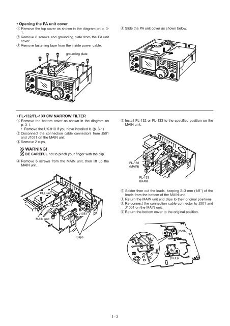
• Opening the PA unit cover<br />
q Remove the top cover as shown in the diagram on p. 3-<br />
1.<br />
w Remove 8 screws and grounding plate from the PA unit<br />
cover.<br />
e Remove fastening tape from the inside power cable.<br />
r Slide the PA unit cover as shown below.<br />
grounding plate<br />
• FL-132/FL-133 CW NARROW FILTER<br />
q Remove the bottom cover as shown in the diagram on<br />
p. 3-1.<br />
• Remove the UX-910 if you have installed it. (p. 3-1)<br />
w Disconnect the connection cable connectors from J501<br />
and J1051 on the MAIN unit.<br />
e Remove 2 clips.<br />
t Install FL-132 or FL-133 to the specified position on the<br />
MAIN unit.<br />
WARNING!<br />
BE CAREFUL not to pinch your finger with the clip.<br />
r Remove 6 screws from the MAIN unit, then lift up the<br />
MAIN unit.<br />
FL-132<br />
(MAIN)<br />
FL-133<br />
(SUB)<br />
PLL unit<br />
J501<br />
J1051<br />
y Solder then cut the leads, keeping 2–3 mm (1/8’’) of the<br />
leads from the bottom of the MAIN unit.<br />
u Return the MAIN unit and clips to their original positions.<br />
i Re-connect the connection cable connector to J501 and<br />
J1051 on the MAIN unit.<br />
o Return the bottom cover to the original position.<br />
MAIN unit<br />
(MAIN)<br />
Clips<br />
(SUB)<br />
3 - 2