
You also want an ePaper? Increase the reach of your titles
YUMPU automatically turns print PDFs into web optimized ePapers that Google loves.
4-1-11 NOISE BLANKER CIRCUIT (MAIN UNIT)<br />
The noise blanker circuit detects pulse-type noises, and<br />
stops IF amplifier operation during detection.<br />
A portion of the 10 MHz IF signal from the bandpass filter<br />
(FI51 [Main], FI651 [Sub]) is amplified at the noise amplifier<br />
circuit (Q102, <strong>IC</strong>101, Q101 [Main], Q702, <strong>IC</strong>701, Q701<br />
[Sub]). The amplified signal is rectified at the noise detector<br />
(D371 [Main], D701 [Sub]) for conversion into DC voltage.<br />
The DC voltage is amplified at the DC amplifier circuit (Q105<br />
[Main], Q705 [Sub]) and then applied to the noise blanker<br />
control circuit (Q52, Q107 [Main], Q652, Q707 [Sub]) to stop<br />
amplification of the IF amplifier circuit (Q51 [Main], Q651<br />
[Sub]).<br />
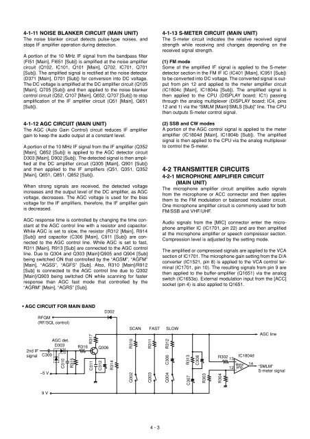
4-1-12 AGC CIRCUIT (MAIN UNIT)<br />
The AGC (Auto Gain Control) circuit reduces IF amplifier<br />
gain to keep the audio output at a constant level.<br />
A portion of the 10 MHz IF signal from the IF amplifier (Q352<br />
[Main], Q852 [Sub]) is applied to the AGC detector circuit<br />
D303 [Main], D902 [Sub]). The detected signal is then amplified<br />
at the DC amplifier circuit (Q305 [Main], Q901 [Sub])<br />
and then applied to the IF amplifiers (Q51, Q351, Q352<br />
[Main], Q651, Q851, Q852 [Sub]).<br />
When strong signals are received, the detected voltage<br />
increases and the output level of the DC amplifier, as AGC<br />
voltage, decreases. The AGC voltage is used for the bias<br />
voltage for the IF amplifiers, therefore, the IF amplifier gain<br />
is decreased.<br />
AGC response time is controlled by changing the time constant<br />
at the AGC control line with a resistor and capacitor.<br />
While AGC is set to slow, the resistor (R312 [Main], R914<br />
[Sub]) and capacitor (C306 [Main], C911 [Sub]) are connected<br />
to the AGC control line. While AGC is set to fast,<br />
R311 [Main], R913 [Sub] are connected to the AGC control<br />
line. Due to Q304 and Q303 [Main]/Q905 and Q904 [Sub]<br />
being switched ON that controlled by the “AGSM”, “AGFM”<br />
[Main], “AGSS”, “AGFS” [Sub]. Also, R310 [Main]/R912<br />
[Sub] is connected to the AGC control line due to Q302<br />
[Main]/Q903 being switched ON while scanning for faster<br />
response than AGC fast mode that controlled by the<br />
“AGRM” [Main], “AGRS” [Sub].<br />
4-1-13 S-METER CIRCUIT (MAIN UNIT)<br />
The S-meter circuit indicates the relative received signal<br />
strength while receiving and changes depending on the<br />
received signal strength.<br />
(1) FM mode<br />
Some of the amplified IF signal is applied to the S-meter<br />
detector section in the FM IF <strong>IC</strong> (<strong>IC</strong>401 [Main], <strong>IC</strong>951 [Sub])<br />
to be converted into DC voltage. The converted signal is output<br />
from pin 12 and applied to the meter amplifier circuit<br />
(<strong>IC</strong>1804c [Main], <strong>IC</strong>1804a [Sub]). The amplified signal is<br />
then applied to the CPU (DISPLAY board; <strong>IC</strong>1) passing<br />
through the analog multiplexer (DISPLAY board; <strong>IC</strong>4, pins<br />
12 and 1) via the “SMLM [Main]/SMLS [Sub]” line. The CPU<br />
then outputs S-meter control signal.<br />
(2) SSB and CW modes<br />
A portion of the AGC control signal is applied to the meter<br />
amplifier (<strong>IC</strong>1804d [Main], <strong>IC</strong>1804b [Sub]). The amplified<br />
signal is then applied to the CPU via the analog multiplexer<br />
to control the S-meter.<br />
4-2 TRANSMITTER CIRCUITS<br />
4-2-1 M<strong>IC</strong>ROPHONE AMPLIFIER CIRCUIT<br />
(MAIN UNIT)<br />
The microphone amplifier circuit amplifies audio signals<br />
from the microphone or ACC connector and then applies<br />
them to the FM modulation or balanced modulator circuit.<br />
One microphone amplifier circuit is commonly used for both<br />
FM/SSB and VHF/UHF.<br />
Audio signals from the [M<strong>IC</strong>] connector enter the microphone<br />
amplifier <strong>IC</strong> (<strong>IC</strong>1701, pin 22) and are then amplified<br />
at the microphone amplifier or speech compressor section.<br />
Compression level is adjusted by the setting mode.<br />
The amplified or compressed signals are applied to the VCA<br />
section of <strong>IC</strong>1701. The microphone gain setting from the D/A<br />
converter (<strong>IC</strong>1521, pin 8) is applied to the VCA control terminal<br />
(<strong>IC</strong>1701, pin 10). The resulting signals from pin 9 are<br />
then applied to the buffer-amplifier (Q1651) via the analog<br />
switch (<strong>IC</strong>1653a). External modulation input from the [ACC]<br />
socket (pin 4) is also applied to Q1651.<br />
• AGC CIRCUIT FOR MAIN BAND<br />
2nd IF<br />
signal<br />
RFGM<br />
(RF/SQL control)<br />
C309<br />
–5 V<br />
AGC det.<br />
D303<br />
C310<br />
R315<br />
R316<br />
R317<br />
C311<br />
Q306<br />
C312<br />
D302<br />
R314<br />
SCAN<br />
R310<br />
Q302<br />
R311<br />
Q303<br />
FAST<br />
SLOW<br />
C306 R312<br />
Q304<br />
C307 R313<br />
C308<br />
R303<br />
R302 <strong>IC</strong>1804d<br />
13<br />
+<br />
Meter 14<br />
12 amp.<br />
–<br />
R304<br />
AGC line<br />
“SMLM”<br />
S-meter signal<br />
9 V<br />
4 - 3