
Create successful ePaper yourself
Turn your PDF publications into a flip-book with our unique Google optimized e-Paper software.
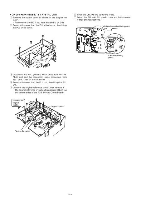
• CR-293 HIGH STABILITY CRYSTAL UNIT<br />
q Remove the bottom cover as shown in the diagram on<br />
p. 3-1.<br />
• Remove the UX-910 if you have installed it. (p. 3-1)<br />
w Remove 6 screws from the PLL shield cover, then lift up<br />
the PLL shield cover.<br />
y Install the CR-293 and solder the leads.<br />
u Return the PLL unit, PLL shield cover and bottom cover<br />
to their original positions.<br />
Original crystal soldering point<br />
PLL shield<br />
cover<br />
CR-293 soldering<br />
points<br />
e Disconnect the FFC (Flexible Flat Cable) from the DIS-<br />
PLAY unit and the connection cable connectors from<br />
J501 and J1051 on the MAIN unit.<br />
r Remove 5 screws from the PLL unit, then lift up the PLL<br />
unit.<br />
t Unsolder the original reference crystal, then remove it.<br />
• The original reference crystal unit is soldered at both top<br />
and bottom sides of the PCB (Printed Circuit Board).<br />
Unsolder the<br />
original<br />
crystal.<br />
CR-293<br />
Original crystal<br />
J501<br />
J1051<br />
Flexible flat cable<br />
3 - 4