NAT-MCH Users Manual Version 1.10
NAT-MCH Users Manual Version 1.10
NAT-MCH Users Manual Version 1.10

Create successful ePaper yourself
Turn your PDF publications into a flip-book with our unique Google optimized e-Paper software.
<strong>NAT</strong>-<strong>MCH</strong> – <strong>Users</strong> <strong>Manual</strong><br />
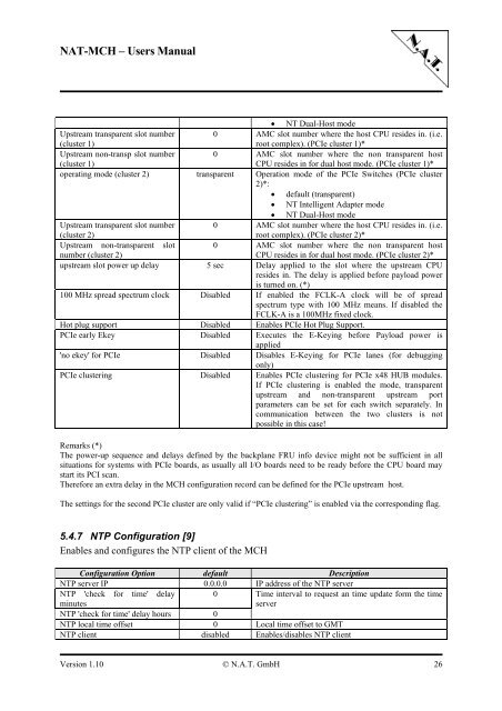
• NT Dual-Host mode<br />
Upstream transparent slot number 0 AMC slot number where the host CPU resides in. (i.e.<br />
(cluster 1)<br />
root complex). (PCIe cluster 1)*<br />
Upstream non-transp slot number 0 AMC slot number where the non transparent host<br />
(cluster 1)<br />
CPU resides in for dual host mode. (PCIe cluster 1)*<br />
operating mode (cluster 2) transparent Operation mode of the PCIe Switches (PCIe cluster<br />
2)*:<br />
• default (transparent)<br />
• NT Intelligent Adapter mode<br />
• NT Dual-Host mode<br />
Upstream transparent slot number 0 AMC slot number where the host CPU resides in. (i.e.<br />
(cluster 2)<br />
root complex). (PCIe cluster 2)*<br />
Upstream non-transparent slot 0 AMC slot number where the non transparent host<br />
number (cluster 2)<br />
CPU resides in for dual host mode. (PCIe cluster 2)*<br />
upstream slot power up delay 5 sec Delay applied to the slot where the upstream CPU<br />
resides in. The delay is applied before payload power<br />
is turned on. (*)<br />
100 MHz spread spectrum clock Disabled If enabled the FCLK-A clock will be of spread<br />
spectrum type with 100 MHz means. If disabled the<br />
FCLK-A is a 100MHz fixed clock.<br />
Hot plug support Disabled Enables PCIe Hot Plug Support.<br />
PCIe early Ekey Disabled Executes the E-Keying before Payload power is<br />
applied<br />
'no ekey' for PCIe Disabled Disables E-Keying for PCIe lanes (for debugging<br />
only)<br />
PCIe clustering Disabled Enables PCIe clustering for PCIe x48 HUB modules.<br />
If PCIe clustering is enabled the mode, transparent<br />
upstream and non-transparent upstream port<br />
parameters can be set for each switch separately. In<br />
communication between the two clusters is not<br />
possible in this case!<br />
Remarks (*)<br />
The power-up sequence and delays defined by the backplane FRU info device might not be sufficient in all<br />
situations for systems with PCIe boards, as usually all I/O boards need to be ready before the CPU board may<br />
start its PCI scan.<br />
Therefore an extra delay in the <strong>MCH</strong> configuration record can be defined for the PCIe upstream host.<br />
The settings for the second PCIe cluster are only valid if “PCIe clustering” is enabled via the corresponding flag.<br />
5.4.7 NTP Configuration [9]<br />
Enables and configures the NTP client of the <strong>MCH</strong><br />
Configuration Option default Description<br />
NTP server IP 0.0.0.0 IP address of the NTP server<br />
NTP 'check for time' delay 0 Time interval to request an time update form the time<br />
minutes<br />
server<br />
NTP 'check for time' delay hours 0<br />
NTP local time offset 0 Local time offset to GMT<br />
NTP client disabled Enables/disables NTP client<br />
<strong>Version</strong> <strong>1.10</strong> © N.A.T. GmbH 26