
You also want an ePaper? Increase the reach of your titles
YUMPU automatically turns print PDFs into web optimized ePapers that Google loves.
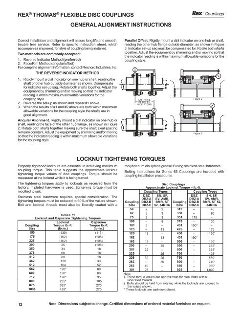
REX ® THOMAS ® FLEXIBLE DISC COUPLINGS<br />
GENERAL ALIGNMENT INSTRUCTIONS<br />
<strong>Couplings</strong><br />
Correct installation and alignment will assure long life and smooth,<br />
trouble free service. Refer to specific instruction sheet, which<br />
accompanies shipment, for style of coupling being installed.<br />
Two methods are commonly accepted:<br />
1. Reverse Indicator Method (preferred)<br />
2. Face/Rim Method (angular/offset)<br />
For complete alignment information, contact Rexnord Industries, Inc.<br />
THE REVERSE INDICATOR METHOD<br />
1. Rigidly mount a dial indicator on one hub or shaft, reading the<br />
shaft or other hub out side diameter as shown. Compensate<br />
for indicator set-up sag. Rotate both shafts together. Adjust the<br />
equipment by shimming and/or moving so that the indicator<br />
reading is within maximum allowable variations for the<br />
coupling style.<br />
2. Reverse the set-up as shown and repeat #1 above.<br />
3. When the results of #1 and #2 above are both within maximum<br />
allowable variations for the coupling style the shafts are in<br />
good alignment.<br />
Angular Alignment. Rigidly mount a dial indicator on one hub or<br />
shaft, reading the face of the other hub flange, as shown in Figure<br />
2. Rotate both shafts together making sure the shaft axial spacing<br />
remains constant. Adjust the equipment by shimming and/or moving<br />
so that the indicator reading is within maximum allowable variations<br />
for the coupling style.<br />
Parallel Offset. Rigidly mount a dial indicator on one hub or shaft,<br />
reading the other hub flange outside diameter, as shown in Figure<br />
3. Indicator set-up sag must be compensated for. Rotate both shafts<br />
together. Adjust the equipment by shimming and/or moving so that<br />
the indicator reading is within maximum allowable variations for the<br />
coupling style.<br />
DISTANCE<br />
BETWEEN<br />
INDICATORS<br />
Figure 2<br />
Figure 3<br />
Properly tightened locknuts are essential in achieving maximum<br />
coupling torque. This table suggests the approximate locknut<br />
tightening torque values of disc couplings. Torque should be<br />
measured at the locknut while it is being turned.<br />
The tightening torques apply to locknuts as received from the<br />
factory. If plated hardware is used, tightening torque must be<br />
modified to suit.<br />
Stainless steel hardware requires special consideration. The<br />
tightening torques must be reduced to 60% of the values shown.<br />
Bolt and locknut threads must also be liberally coated with a<br />
Series 71<br />
Locknut and Capscrew Tightening Torques<br />
Coupling<br />
Size<br />
Locknut<br />
Torque lb.-ft.<br />
(lb.-in.)<br />
Capscrew<br />
Torque lb.-ft.<br />
(lb.-in.)<br />
150<br />
( 130)<br />
(113)<br />
175<br />
( 162)<br />
(108)<br />
225<br />
( 162)<br />
(108)<br />
300<br />
25<br />
(108)<br />
350<br />
34<br />
18<br />
376<br />
60<br />
18<br />
412<br />
80<br />
18<br />
462<br />
130<br />
33<br />
512<br />
164<br />
52<br />
562<br />
190*<br />
80<br />
600<br />
190*<br />
80<br />
712<br />
190*<br />
95<br />
800<br />
255*<br />
165<br />
875<br />
335*<br />
270<br />
1038<br />
425*<br />
270<br />
LOCKNUT TIGHTENING TORQUES<br />
molybdenum disulphide grease if using stainless steel hardware.<br />
Bolting instructions for Series 63 <strong>Couplings</strong> are included with<br />
coupling installation procedures.<br />
Disc <strong>Couplings</strong><br />
Approximate Locknut Torque – lb.-ft.<br />
Coupling Types<br />
Coupling Types<br />
Coupling<br />
Size<br />
DBZ<br />
DBZ-A<br />
DBZ-B<br />
DBZ-C<br />
SN, SF,<br />
SV, AMR,<br />
BMR, ST<br />
52, 54RDG<br />
Coupling<br />
Size<br />
DBZ<br />
DBZ-A<br />
DBZ-B<br />
DBZ-C<br />
SN, SF,<br />
SV, AMR,<br />
BMR, ST 52,<br />
54RDG<br />
50<br />
2 2 312<br />
– 40<br />
62<br />
3 3 350<br />
– 95<br />
75<br />
3 3 351<br />
175<br />
–<br />
100<br />
– 8 375<br />
– 130<br />
101<br />
8 – 401<br />
150*<br />
–<br />
125<br />
– 13<br />
425<br />
– 175<br />
126<br />
13<br />
– 450<br />
– 150*<br />
162<br />
– 13<br />
451<br />
190*<br />
–<br />
163<br />
13<br />
– 500<br />
– 190*<br />
200<br />
– 25<br />
550<br />
– 255*<br />
201<br />
25<br />
– 600<br />
– 335*<br />
225<br />
– 25<br />
700<br />
– 425*<br />
226<br />
30<br />
25<br />
750<br />
– 560*<br />
262<br />
– 30<br />
800<br />
– 740*<br />
263<br />
40<br />
– 850<br />
– 950*<br />
301<br />
95<br />
– 925<br />
– 1,800<br />
Note:<br />
1. These torque values are approximate for steel bolts with oil<br />
lubricated threads.<br />
2. Bolts should be held from rotating while the locknuts are torqued to<br />
the values shown.<br />
* These locknuts are cadmium plated.<br />
12<br />
Note: Dimensions subject to change. Certified dimensions of ordered material furnished on request.