
You also want an ePaper? Increase the reach of your titles
YUMPU automatically turns print PDFs into web optimized ePapers that Google loves.
<strong>Couplings</strong><br />
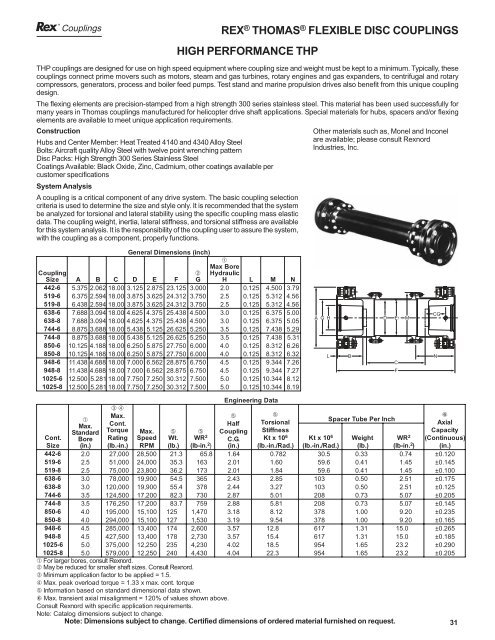
REX ® THOMAS ® FLEXIBLE DISC COUPLINGS<br />
HIGH PERFORMANCE THP<br />
THP couplings are designed for use on high speed equipment where coupling size and weight must be kept to a minimum. Typically, these<br />
couplings connect prime movers such as motors, steam and gas turbines, rotary engines and gas expanders, to centrifugal and rotary<br />
compressors, generators, process and boiler feed pumps. Test stand and marine propulsion drives also benefit from this unique coupling<br />
design.<br />
The flexing elements are precision-stamped from a high strength 300 series stainless steel. This material has been used successfully for<br />
many years in Thomas couplings manufactured for helicopter drive shaft applications. Special materials for hubs, spacers and/or flexing<br />
elements are available to meet unique application requirements.<br />
Construction<br />
Hubs and Center Member: Heat Treated 4140 and 4340 Alloy Steel<br />
Bolts: Aircraft quality Alloy Steel with twelve point wrenching pattern<br />
Disc Packs: High Strength 300 Series Stainless Steel<br />
Coatings Available: Black Oxide, Zinc, Cadmium, other coatings available per<br />
customer specifications<br />
System Analysis<br />
A coupling is a critical component of any drive system. The basic coupling selection<br />
criteria is used to determine the size and style only. It is recommended that the system<br />
be analyzed for torsional and lateral stability using the specific coupling mass elastic<br />
data. The coupling weight, inertia, lateral stiffness, and torsional stiffness are available<br />
for this system analysis. It is the responsibility of the coupling user to assure the system,<br />
with the coupling as a component, properly functions.<br />
General Dimensions (inch)<br />
Other materials such as, Monel and Inconel<br />
are available; please consult Rexnord<br />
Industries, Inc.<br />
Coupling<br />
Size<br />
A B C D E F<br />
➀<br />
Max<br />
Bore<br />
➁ Hydraulic<br />
G H L M N<br />
442-6<br />
5.375<br />
2.062<br />
18.00<br />
3.125<br />
2.875<br />
23.125<br />
3.000<br />
2.<br />
0 0.125<br />
4.500<br />
3.79<br />
519-6<br />
6.375<br />
2.594<br />
18.00<br />
3.875<br />
3.625<br />
24.312<br />
3.750<br />
2.<br />
5 0.125<br />
5.312<br />
4.56<br />
519-8<br />
6.438<br />
2.594<br />
18.00<br />
3.875<br />
3.625<br />
24.312<br />
3.750<br />
2.<br />
5 0.125<br />
5.312<br />
4.56<br />
638-6<br />
7.688<br />
3.094<br />
18.00<br />
4.625<br />
4.375<br />
25.438<br />
4.500<br />
3.<br />
0 0.125<br />
6.375<br />
5.00<br />
638-8<br />
7.688<br />
3.094<br />
18.00<br />
4.625<br />
4.375<br />
25.438<br />
4.500<br />
3.<br />
0 0.125<br />
6.375<br />
5.05<br />
744-6<br />
8.875<br />
3.688<br />
18.00<br />
5.438<br />
5.125<br />
26.625<br />
5.250<br />
3.<br />
5 0.125<br />
7.438<br />
5.29<br />
744-8<br />
8.875<br />
3.688<br />
18.00<br />
5.438<br />
5.125<br />
26.625<br />
5.250<br />
3.<br />
5 0.125<br />
7.438<br />
5.31<br />
850-6<br />
10.125<br />
4.188<br />
18.00<br />
6.250<br />
5.875<br />
27.750<br />
6.000<br />
4.<br />
0 0.125<br />
8.312<br />
6.26<br />
850-8<br />
10.125<br />
4.188<br />
18.00<br />
6.250<br />
5.875<br />
27.750<br />
6.000<br />
4.<br />
0 0.125<br />
8.312<br />
6.32<br />
948-6<br />
11.43<br />
8 4.688<br />
18.00<br />
7.000<br />
6.562<br />
28.875<br />
6.750<br />
4.<br />
5 0.125<br />
9.344<br />
7.26<br />
948-8<br />
11.43<br />
8 4.688<br />
18.00<br />
7.000<br />
6.562<br />
28.875<br />
6.750<br />
4.<br />
5 0.125<br />
9.344<br />
7.27<br />
1025-6<br />
12.500<br />
5.28118.00<br />
7.750<br />
7.250<br />
30.312<br />
7.500<br />
5.<br />
0 0.125<br />
10.344<br />
8.12<br />
1025-8<br />
12.500<br />
5.28118.00<br />
7.750<br />
7.250<br />
30.312<br />
7.500<br />
5.<br />
0 0.125<br />
10.344<br />
8.19<br />
A G H<br />
L<br />
B<br />
D<br />
E<br />
C<br />
F<br />
M<br />
CG<br />
N<br />
Engineering Data<br />
Max.<br />
➄<br />
➄<br />
6<br />
➀<br />
Max.<br />
Cont.<br />
Half Torsional<br />
Spacer Tube Per Inch<br />
Axial<br />
Standard<br />
Torque Max.<br />
➄ ➄ Coupling Stiffness<br />
Capacity<br />
Cont. B ore Rating Speed<br />
W t.<br />
WR<br />
2<br />
C .G. Kt<br />
x 106<br />
Kt<br />
x 106<br />
Weight WR<br />
2 (Continuous)<br />
Size ( in. ) ( l b.-in.<br />
) RPM<br />
(lb.)<br />
( lb-in.<br />
) ( in. ) (lb.-in./Rad.) (lb.-in./Rad.) (lb.) ( lb-in.<br />
) (in.)<br />
➂➃<br />
442-6<br />
2.<br />
0 27,000<br />
28,500<br />
21.<br />
3 65.<br />
8 1.64<br />
0.782<br />
30.<br />
5 0.33<br />
0.74<br />
±0.120<br />
519-6<br />
2.<br />
5 51,000<br />
24,000<br />
35.<br />
3 163<br />
2.01<br />
1.60<br />
59.<br />
6 0.41<br />
1.45<br />
±0.145<br />
519-8<br />
2.<br />
5 75,000<br />
23,800<br />
36.<br />
2 173<br />
2.01<br />
1.84<br />
59.<br />
6 0.41<br />
1.45<br />
±0.100<br />
638-6<br />
3.<br />
0 78,000<br />
19,900<br />
54.<br />
5 365<br />
2.43<br />
2.85<br />
103<br />
0.50<br />
2.51<br />
±0.175<br />
638-8<br />
3.<br />
0 120,000<br />
19,900<br />
55.<br />
4 378<br />
2.44<br />
3.27<br />
103<br />
0.50<br />
2.51<br />
±0.125<br />
744-6<br />
3.<br />
5 124,500<br />
17,200<br />
82.<br />
3 730<br />
2.87<br />
5.01<br />
208<br />
0.73<br />
5.07<br />
±0.205<br />
744-8<br />
3.<br />
5 176,250<br />
17,200<br />
83.<br />
7 759<br />
2.88<br />
5.81<br />
208<br />
0.73<br />
5.07<br />
±0.145<br />
850-6<br />
4.<br />
0 195,000<br />
15,100<br />
125<br />
1, 470<br />
3.18<br />
8.12<br />
378<br />
1.00<br />
9.20<br />
±0.235<br />
850-8<br />
4.<br />
0 294,000<br />
15,100<br />
127<br />
1, 530<br />
3.19<br />
9.54<br />
378<br />
1.00<br />
9.20<br />
±0.165<br />
948-6<br />
4.<br />
5 285,000<br />
13,400<br />
174<br />
2, 600<br />
3.57<br />
12.<br />
8<br />
617<br />
1.31<br />
15.<br />
0 ±0.265<br />
948-8<br />
4.<br />
5 427,500<br />
13,400<br />
178<br />
2, 730<br />
3.57<br />
15.<br />
4<br />
617<br />
1.31<br />
15.<br />
0 ±0.185<br />
1025-6<br />
5.<br />
0 375,000<br />
12,250<br />
235<br />
4, 230<br />
4.02<br />
18.<br />
5<br />
954<br />
1.65<br />
23.<br />
2 ±0.290<br />
1025-8<br />
5.<br />
0 579,000<br />
12,250<br />
240<br />
4, 430<br />
4.04<br />
22.<br />
3<br />
954<br />
1.65<br />
23.<br />
2 ±0.205<br />
➀ For larger bores, consult Rexnord .<br />
➁ May be reduced for smaller shaft sizes. Consult Rexnord .<br />
➂ Minimum application factor to be applied = 1.5.<br />
➃ Max. peak overload torque = 1.33 x max. cont. torque<br />
➄ Information based on standard dimensional data shown.<br />
6 Max. transient axial misalignment = 120% of values shown above.<br />
Consult Rexnord with specific application requirements.<br />
Note: Catalog dimensions subject to change.<br />
Note: Dimensions subject to change. Certified dimensions of ordered material furnished on request. 31