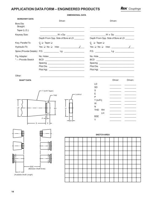
APPLICATION DATA FORM – ENGINEERED PRODUCTS <strong>Couplings</strong> DIMENSIONAL DATA BORE/KWY DATA Driver: Driven: Bore Dia: Straight: ___________________________________ ___________________________________ Taper (L.D.): ___________________________________ ___________________________________ Keyway Size: ______________W. x Dp. ______________ ____________W. x Dp. _______________ Depth From Opp. Side of Bore at LD ________ Depth From Opp. Side of Bore at LD _______ Kwy. Parallel To: C L ❏ Taper ❏ C L ❏ Taper ❏ Hydraulic Fit: Yes ❏ No ❏ Inter. ___________________ Yes ❏ No ❏ Inter. __________________ Spine (Provide Details): P.D. ____________ Lg. ________________ P.D. ____________ Lg. _______________ Fig. Adapter: No. Holes ____________________________ No. Hole ____________________________ * — Provide Sketch BCD _______________________________ BCD ______________________________ Spacing _____________________________ Spacing ____________________________ Pilot Dia. ____________________________ Pilot Dia. ___________________________ Pilot Hgt. ____________________________ Pilot Hgt. ___________________________ Other: ___________________________________ ___________________________________ SHAFT DATA Driver: Driven: LD S T (In/Ft Taper) THD SD P E N W Locknut LD _________ _________ SD _________ _________ S _________ _________ E _________ _________ P _________ _________ T (In/Ft) _________ _________ W _________ _________ N _________ _________ THD RH _________ _________ LH _________ _________ BSE _________ _________ V _________ _________ SKETCH AREA BSE (Between Shaft Ends) V (Available Shaft Length) 14
<strong>Couplings</strong> REX ® THOMAS ® FLEXIBLE DISC COUPLINGS CLOSE-COUPLED SERIES 54RDG Series 54RDG couplings are reduced diameter gear and grid replacement couplings. Applications include any situation where the overall shaft to shaft spacing is minimal. The center member of the 54RDG is split axially, which permits maintenance of the couplings without moving the hubs or the connected equipment. Center member is piloted into the adapter providing high speed potential at high torque density. Construction Hubs and Center members: Carbon Steel Bolts: Alloy Steel Disc Packs: Stainless Steel Coatings Available: Black Oxide, Zinc, Cadmium When Specified, Series 54RDG couplings meet all requirements of API 610, or API 671. If application requires API specification, please consult Rexnord Industries, Inc. Other materials such as Tomaloy, Monel and Inconel are available; please consult Rexnord Industries, Inc. Misalignment: 1 /3° per disc pack **NEW DESIGN** **INCREASED TORQUE RATINGS** General Dimensions (inch) Coupling M ax Bore* M ax Bore* Size Interna l External A B C C1* * F F1* * H N G C 2** * F2** * 125 1.188 1.375 3.81 1.88 0.12 1.75 3.88 4.94 0.17 0.27 1.75 3.38 6.00 162 1.625 1.875 4.47 1.88 0.12 1.77 3.88 5.40 0.17 0.29 2.34 3.42 6.92 200 2.250 2.250 5.56 2.12 0.12 1.96 4.36 6.14 0.22 0.36 3.25 3.80 7.92 225 2.375 2.625 5.88 2.19 0.12 2.03 4.50 6.84 0.22 0.36 3.50 3.94 9.18 262 2.750 3.125 6.88 2.59 0.19 2.42 5.37 7.89 0.25 0.47 4.12 4.6510.41 312 3.375 3.625 7.84 2.84 0.19 2.62 5.87 8.84 0.30 0.50 5.00 5.05 11.81 350 3.750 4.000 8.78 3.28 0.25 3.06 6.81 10.09 0.34 0.54 5.50 5.8713.37 375 4.188 4.500 9.72 3.56 0.25 3.26 7.37 10.82 0.39 0.59 6.06 6.2714.27 425 4.500 4.750 10.50 3.97 0.25 3.61 8.19 11.83 0.42 0.62 6.56 6.9715.47 450 4.750 5.125 11.31 4.50 0.31 4.15 9.31 13.15 0.47 0.71 7.00 7.9916.99 500 5.000 5.375 12.88 4.78 0.31 4.32 9.87 14.10 0.50 0.78 7.88 8.3318.33 550 5.500 6.000 14.44 5.37 0.38 4.8711.12 15.74 0.58 0.91 8.75 9.3620.36 600 6.000 6.500 16.00 6.00 0.38 5.4012.38 17.40 0.67 0.98 9.3110.4222.42 700 7.000 7.500 18.25 7.00 0.38 6.2214.38 20.22 0.75 1.2010.8812.0626.06 750 7.500 8.000 19.81 7.75 0.50 7.0016.00 22.25 0.84 1.2711.7513.5 028.50 800 8.000 8.750 21.50 8.25 0.50 7.3717.00 23.87 0.91 1.3412.5014.2 430.74 850 8.500 9.250 23.00 8.88 0.56 7.9718.32 25.60 1.00 1.4013.1915.3832.88 925 9.000 10.125 25.00 9.91 0.62 8.9120.44 28.32 1.09 1.5014.1217.2 036.20 * Non-bored hubs available upon request. ** Hubs may be reversed for alternate shaft spacing *** Both hubs reversed A MAX. BORE EXTERNAL H C C2 B F F2 C1 N F1 Patent Pending MAX. BORE INTERNAL G Engineering Data Max Horsepower Per 100 RPM Maximum RPM Maximum Peak Service Continuous Overload ➁ ➄ Coupling Factor ➀ ➀ Torque Torque W eight WR 2 Axial Capacity Size 1 Not Balanced Balanced (lb.-in.) (lb.-in.) ( lb. ) ( lb.-in. 2 ) (in.) 125 4. 3 4,600 10,500 2,700 5,400 6. 9 12. 5 ±0.036 162 8. 5 4,200 9,700 5,350 10,700 9. 3 24. 0 ±0.036 200 16. 7 3,800 8,600 10,500 21,000 16 67. 0 ±0.036 225 27. 8 3,700 8,400 17,500 35,000 19 85. 0 ±0.036 262 52. 1 3,600 7,400 32,830 65,660 31 192 ±0.043 312 81. 6 3,000 6,700 51,400 102,800 46 384 ±0.051 350 106 2,800 6,200 66,900 133,800 66 689 ±0.056 375 159 2,500 4,800 100,300 200,600 88 1,160 ±0.062 425 213 2,300 5,400 134,300 268,600 117 1,780 ±0.067 450 239 2,200 5,000 150,400 300,800 154 2,690 ±0.072 500 391 2,000 4,600 246,400 492,800 224 4,970 ±0.082 550 524 1,900 4,200 330,400 660,800 324 8,970 ±0.092 600 688 1,800 3,900 433,800 867,600 437 14,900 ±0.102 700 1, 071 1,700 3,600 674,800 1,349,600 657 29,000 ±0.115 750 1, 331 1,550 3,400 838,800 1,677,600 839 43,400 ±0.125 800 1, 712 1,450 3,200 1,078,700 2,157,400 1,040 63,900 ±0.136 850 2, 020 1,350 3,000 1,273,000 2,546,000 1,260 88,900 ±0.144 925 2, 735 1,300 2,800 1,724,000 3,448,000 1,690 140,000 ±0.156 F or ordering instructions, see Page 10-11 . ➀ See page 7 for explanation of RPM limits and balancing recommendations . ➁ Weight and WR2 with standard length hubs, maximum bore and standard "C". ➂ Extended hub length is designed longer in order to include a counter-bore for the threaded extension on a tapered shaft . ➃ Large hub length. For sizes not shown, consult Rexnord . ➄ All Thomas disc couplings meet NEMA frame sleeve bearing motor specifications without modifications or the addition of end-float restricting devices . Note: Dimensions subject to change. Certified dimensions of ordered material furnished on request. 15