15-B Maintenance Mnl, GFZ-62075E/03 - Automation Service Srl
15-B Maintenance Mnl, GFZ-62075E/03 - Automation Service Srl
15-B Maintenance Mnl, GFZ-62075E/03 - Automation Service Srl

Create successful ePaper yourself
Turn your PDF publications into a flip-book with our unique Google optimized e-Paper software.
3. TROUBLESHOOTING AND ACTION TO BE TAKEN<br />
B–<strong>62075E</strong>/<strong>03</strong><br />
Item<br />
(How to reset the error)<br />
(a) The machine can be moved only toward the normal operating ranges.<br />
(b) When the machine has stopped in the restricted zone and cannot escape it, press the emergency<br />
stop button to reset the alarm. Then, specify G23 on the MDI panel to disable the stored stroke<br />
limit function and move the machine in the jog mode.<br />
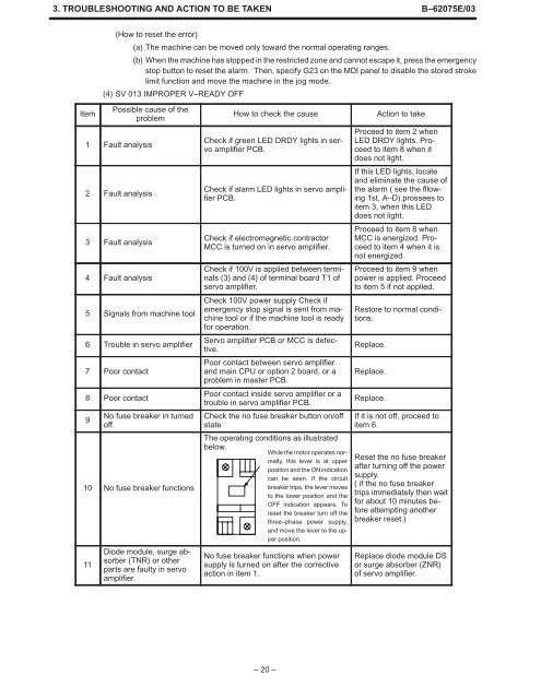
(4) SV 013 IMPROPER V–READY OFF<br />
Possible cause of the<br />
How to check the cause<br />
Action to take<br />
problem<br />
1 Fault analysis<br />
2 Fault analysis<br />
3 Fault analysis<br />
4 Fault analysis<br />
5 Signals from machine tool<br />
6 Trouble in servo amplifier<br />
7 Poor contact<br />
8 Poor contact<br />
9<br />
No fuse breaker in turned<br />
off.<br />
10 No fuse breaker functions<br />
11<br />
Diode module, surge absorber<br />
(TNR) or other<br />
parts are faulty in servo<br />
amplifier.<br />
Check if green LED DRDY lights in servo<br />
amplifier PCB.<br />
Check if alarm LED lights in servo amplifier<br />
PCB.<br />
Check if electromagnetic contractor<br />
MCC is turned on in servo amplifier.<br />
Check if 100V is applied between terminals<br />
(3) and (4) of terminal board T1 of<br />
servo amplifier.<br />
Check 100V power supply Check if<br />
emergency stop signal is sent from machine<br />
tool or if the machine tool is ready<br />
for operation.<br />
Servo amplifier PCB or MCC is defective.<br />
Poor contact between servo amplifier<br />
and main CPU or option 2 board, or a<br />
problem in master PCB.<br />
Poor contact inside servo amplifier or a<br />
trouble in servo amplifier PCB.<br />
Check the no fuse breaker button on/off<br />
state<br />
The operating conditions as illustrated<br />
below.<br />
While the motor operates normally,<br />
this lever is at upper<br />
position and the ON indication<br />
can be seen. If the circuit<br />
breaker trips, the lever moves<br />
to the lower position and the<br />
OFF indication appears. To<br />
reset the breaker turn off the<br />
three–phase power supply,<br />
and move the lever to the upper<br />
position.<br />
No fuse breaker functions when power<br />
supply is turned on after the corrective<br />
action in item 1.<br />
Proceed to item 2 when<br />
LED DRDY lights. Proceed<br />
to item 8 when it<br />
does not light.<br />
If this LED lights, locate<br />
and eliminate the cause of<br />
the alarm ( see the fllowing<br />
1st, A–D).prossees to<br />
item 3, when this LED<br />
does not light.<br />
Proceed to item 8 when<br />
MCC is energized. Proceed<br />
to item 4 when it is<br />
not energized.<br />
Proceed to item 9 when<br />
power is applied. Proceed<br />
to item 5 if not applied.<br />
Restore to normal conditions.<br />
Replace.<br />
Replace.<br />
Replace.<br />
If it is not off, proceed to<br />
item 6.<br />
Reset the no fuse breaker<br />
after turning off the power<br />
supply.<br />
( if the no fuse breaker<br />
trips immediately then wait<br />
for about 10 minutes before<br />
attempting another<br />
breaker reset.)<br />
Replace diode module DS<br />
or surge absorber (ZNR)<br />
of servo amplifier.<br />
– 20 –