Seepage Modeling with SEEP/W - GeoStudio 2007 version 7.22
Seepage Modeling with SEEP/W - GeoStudio 2007 version 7.22
Seepage Modeling with SEEP/W - GeoStudio 2007 version 7.22

Create successful ePaper yourself
Turn your PDF publications into a flip-book with our unique Google optimized e-Paper software.
Chapter 3: Geometry and Meshing<br />
<strong>SEEP</strong>/W<br />
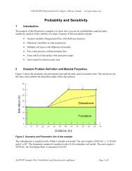
The discussion now will focus on how to apply an interface region to a line object. There are two ways to<br />
do this. There is a Draw Line Material Properties command in which you can choose a material model<br />
you have defined and apply it to a line by clicking just next to a line as shown in Figure 3-12. You can<br />
assign a different property to either side of a line. If you use this option, you are specifying the material<br />
as well as creating special thin “interface” elements. You can then go back and change the element<br />
thickness from its default value using the Draw Mesh Properties command and choosing the line.<br />
Figure 3-12 Using the Draw Line Material command to assign an interface model to a line<br />
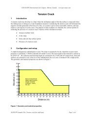
The second option for specifying an interface model on a line is to first create the thin elements and then<br />
assign the material to the line. You can use the Draw Mesh Properties command, select the line, choose<br />
the Generate Interface Elements option and specify an interface element thickness. This process is<br />
illustrated in Figure 3-13.<br />
The actual thickness of the interface elements may or may not have physical meaning but the material<br />
model assigned to them will hold some meaning. If, for example, the interface represents an insulation<br />
layer in TEMP/W, then the thickness is relevant. However, if the interface describes the frictional<br />
behavior between two sliding blocks, then the thickness specified is not factored in the solution and it can<br />
be specified only to satisfy your presentation needs.<br />
Page 32