Seepage Modeling with SEEP/W - GeoStudio 2007 version 7.22
Seepage Modeling with SEEP/W - GeoStudio 2007 version 7.22
Seepage Modeling with SEEP/W - GeoStudio 2007 version 7.22

Create successful ePaper yourself
Turn your PDF publications into a flip-book with our unique Google optimized e-Paper software.
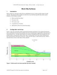
Chapter 3: Geometry and Meshing<br />
<strong>SEEP</strong>/W<br />
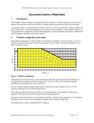
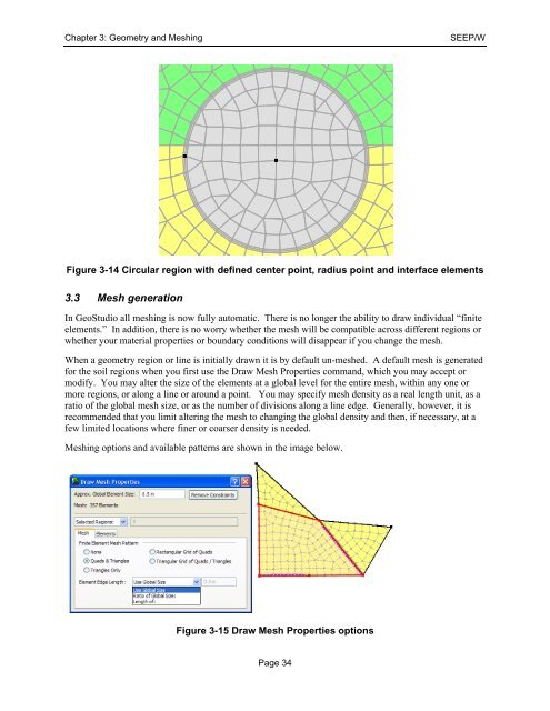
Figure 3-14 Circular region <strong>with</strong> defined center point, radius point and interface elements<br />
3.3 Mesh generation<br />
In <strong>GeoStudio</strong> all meshing is now fully automatic. There is no longer the ability to draw individual “finite<br />
elements.” In addition, there is no worry whether the mesh will be compatible across different regions or<br />
whether your material properties or boundary conditions will disappear if you change the mesh.<br />
When a geometry region or line is initially drawn it is by default un-meshed. A default mesh is generated<br />
for the soil regions when you first use the Draw Mesh Properties command, which you may accept or<br />
modify. You may alter the size of the elements at a global level for the entire mesh, <strong>with</strong>in any one or<br />
more regions, or along a line or around a point. You may specify mesh density as a real length unit, as a<br />
ratio of the global mesh size, or as the number of divisions along a line edge. Generally, however, it is<br />
recommended that you limit altering the mesh to changing the global density and then, if necessary, at a<br />
few limited locations where finer or coarser density is needed.<br />
Meshing options and available patterns are shown in the image below.<br />
Figure 3-15 Draw Mesh Properties options<br />
Page 34