Microsoft Word - Z1 370Z Oil Cooler Kit ... 459KB Sep 11 2010 11:50 ...
Microsoft Word - Z1 370Z Oil Cooler Kit ... 459KB Sep 11 2010 11:50 ...
Microsoft Word - Z1 370Z Oil Cooler Kit ... 459KB Sep 11 2010 11:50 ...

You also want an ePaper? Increase the reach of your titles
YUMPU automatically turns print PDFs into web optimized ePapers that Google loves.
<strong>Z1</strong> Motorsports 1200 Carrollton Villa Rica Hwy Carrollton GA 30<strong>11</strong>6 770.838.7777<br />
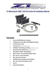
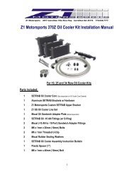
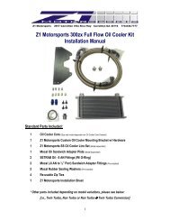
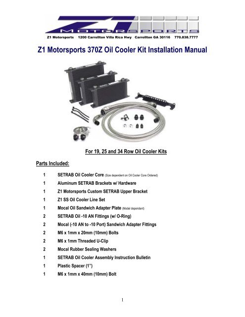
<strong>Z1</strong> Motorsports <strong>370Z</strong> <strong>Oil</strong> <strong>Cooler</strong> <strong>Kit</strong> Installation Manual<br />
For 19, 25 and 34 Row <strong>Oil</strong> <strong>Cooler</strong> <strong>Kit</strong>s<br />
Parts Included:<br />
1 SETRAB <strong>Oil</strong> <strong>Cooler</strong> Core (Size dependent on <strong>Oil</strong> <strong>Cooler</strong> Core Ordered)<br />
1 Aluminum SETRAB Brackets w/ Hardware<br />
1 <strong>Z1</strong> Motorsports Custom SETRAB Upper Bracket<br />
1 <strong>Z1</strong> SS <strong>Oil</strong> <strong>Cooler</strong> Line Set<br />
1 Mocal <strong>Oil</strong> Sandwich Adapter Plate (Model dependent)<br />
2 SETRAB <strong>Oil</strong> -10 AN Fittings (w/ O-Ring)<br />
2 Mocal (-10 AN to -10 Port) Sandwich Adapter Fittings<br />
2 M6 x 1mm x 20mm (10mm) Bolts<br />
2 M6 x 1mm Threaded U-Clip<br />
2 Mocal Rubber Sealing Washers<br />
1 SETRAB <strong>Oil</strong> <strong>Cooler</strong> Assembly Instruction Bulletin<br />
1 Plastic Spacer (1”)<br />
1 M6 x 1mm x 40mm (10mm) Bolt<br />
1
Additional Parts:<br />
1 Quart (1 Liter) Engine <strong>Oil</strong> (Not Included)<br />
2 Additional Zip Ties<br />
Tools Required:<br />
• Assorted Metric Wrenches (10mm – 19mm) • Assorted Metric Sockets (10mm – 19mm)<br />
• Assorted Metric Allen Head Wrenches<br />
• Ratchet<br />
• Assorted Screw Drivers<br />
• Pliers<br />
• Floor Jack • Jack Stands (Minimum of 2)<br />
• Tire removal tools<br />
• Torque Wrench<br />
• Funnel<br />
• Drill<br />
• Assorted Drill Bits<br />
! Space Intentionally Left Blank – Continue to the following page !<br />
2
Installation:<br />
WARNING!: Extreme caution should be taken when performing ANY maintenance or performance upgrades to your<br />
vehicle. Please observe and abide by any Warning or Caution labels placed on the various components and tools used<br />
when servicing your vehicle. If you have any questions regarding the installation or the various components included<br />
with the <strong>Z1</strong> Motorsports <strong>370Z</strong> <strong>Oil</strong> <strong>Cooler</strong> <strong>Kit</strong>, consult with a Professional Mechanic or contact <strong>Z1</strong> Motorsports for more<br />
information.<br />
Installation Note #1:<br />
It is recommended that you perform the <strong>Z1</strong> Motorsports <strong>370Z</strong> <strong>Oil</strong> <strong>Cooler</strong> <strong>Kit</strong> installation at a scheduled interval when<br />
your vehicle requires an <strong>Oil</strong> Change. This due to the fact that the <strong>Oil</strong> Filter must be removed and that some Engine <strong>Oil</strong><br />
will be lost in order to properly install the kit.<br />
*BEFORE YOU BEGIN!<br />
Remove all contents from the <strong>Z1</strong> Motorsports <strong>370Z</strong> <strong>Oil</strong> <strong>Cooler</strong> <strong>Kit</strong> and verify that ALL necessary<br />
hardware is present.<br />
1. Properly raise and support your <strong>370Z</strong> using jack stands and the proper jacking points<br />
on your vehicle’s chassis (Refer to vehicle’s Owner’s Manual)<br />
2. Apply the Parking Brake<br />
3. Disconnect the NEGATIVE (--) Battery Terminal<br />
4. Raise the vehicle’s Hood<br />
5. Remove Front Passenger Side Wheel<br />
6. Remove both the Lower Engine Splash Shield and the Passenger Side Inner Fender<br />
Liner. Refer to the images below for the exact location of the fasteners:<br />
a) Remove the following fasters, high lighted below. Fasters will be an assortment of<br />
10mm screws and Plastic Panel Clips. Use a flat blade screw driver to gently pry the pop<br />
clips up.<br />
3
a) Do not discard the small plastic panel shown here. It will be reinstalled later.<br />
c) Be sure to remove these two plastic panel clips. The one shown in the image below on<br />
the Left will be exposed only after the lower engine shroud is removed. There is also a<br />
plastic panel clip (not shown) at the very top of the fender liner that will also need to be<br />
removed.<br />
4
7. Remove the Front Fascia Radiator Air Guide. This is done be using a flat blade screw<br />
driver and gently popping out the center section of the 7 Plastic Pop Clips located under<br />
the hood. The air guide will simply slide up and out from beneath the front fascia. Refer<br />
to the image below for the location of the plastic pop clips.<br />
8. You will also need to remove the 7 additional Plastic Pop Clips securing the front fascia.<br />
Refer to the image below for the location of the plastic pop clips.<br />
8. Remove the two 10mm Plastic Screws<br />
5
9. Gripping the sides of fascia (circled below) pull the fascia towards you. This part of the<br />
fascia snaps in place and will pop loose when a limited amount of force is applied.<br />
Once free, carefully remove the fascia from the chassis and set aside.<br />
9 (continued). You should see something similar to the image below.<br />
Installation Note #2:<br />
Some individuals find that removing the Front Aluminum Crash Bar and Foam Reinforcement pad eases in the<br />
installation of the <strong>370Z</strong> <strong>Oil</strong> <strong>Cooler</strong> <strong>Kit</strong>s. This is not necessary.<br />
10. Assemble the SETRAB <strong>Oil</strong> <strong>Cooler</strong> Assembly using the supplied hardware and brackets<br />
by following the instructions below:<br />
6
Locate the following parts:<br />
1 SETRAB <strong>Oil</strong> <strong>Cooler</strong> Core (Size dependent on <strong>Oil</strong> <strong>Cooler</strong> Core Ordered)<br />
1 Aluminum SETRAB Brackets w/ Hardware<br />
1 <strong>Z1</strong> Motorsports Custom SETRAB Upper Bracket<br />
a. Using the Aluminum SETRAB Bracket and it supplied hardware. Attach the bracket<br />
to the bottom of the oil cooler (opposite of the end with the fittings). The rotation of<br />
the bracket does not matter. The core can be rotated depending on installation<br />
preferences. Refer to the image below:<br />
b. Locate the <strong>Z1</strong> Motorsports Custom Upper Bracket w/ Hardware (All hardware should<br />
be assembled together for shipping purposes).<br />
7
c. Referring to the images below, you will attach the bracket to the top left hand corner<br />
of the SETRAB <strong>Oil</strong> <strong>Cooler</strong> Core.<br />
Installation Note #3:<br />
Since the core’s position is reversible, it is recommended that the oil cooler core be positioned as close to the A/C<br />
Condenser as possible. The <strong>Z1</strong> Motorsports Custom Upper Bracket can only be installed with the core in this position.<br />
Installatoin Note #3 (Continued):<br />
Refer to the image below for the exact position of the oil cooler brackets. This configuration is<br />
recommended for all 370z/G37’s equipped with either the STILLEN GEN III Intake or a Forced<br />
Induction Setup. Some modifications or reversal of the core support will be necessary when<br />
installing an oil cooler core onto a 370z with the NISMO Brace <strong>Kit</strong> (Nissan Part # E4420-1EK000).<br />
d. Locate the two supplied M6 x 1mm Threaded U-Clips (x2) and two M6 x 1mm x<br />
20mm (10mm) Bolts [These should be threaded into one another for shipping<br />
purposes].<br />
e. Slide the two Threaded U-Clips onto the core support as shown below. You will be<br />
using the two blank spots on the Driver side of the core support (lower).<br />
8
f. You can now, temporarily position the oil cooler core/bracket assembly on the core<br />
support of the vehicle. Using the two M6-1.00 bolts, secure the core support to the<br />
chassis, but DO NOT TIGHTEN DOWN ANY BOLTS.<br />
g. Position the oil cooler core so that the upper bracket’s unused sits just behind the<br />
center core support brace (Vertical steel brace that should be sitting just to the left<br />
of the oil cooler).<br />
h. With the core in place, you will now need to mark the location of the hole that will be<br />
used to attach the Upper <strong>Oil</strong> <strong>Cooler</strong> Core Bracket to the chassis. This hole does not<br />
exist from the factory and will need to be drilled. Customers who have purchased<br />
19 and 25 row oil cooler kits can skip this step if they choose (not recommended),<br />
all customers who have purchased the 34 row oil cooler kit MUST install this bracket.<br />
The oil cooler core will be allowed to move too much without the upper bracket and<br />
could possibly damage the fiberglass core support or A/C Condenser.<br />
9
Installation note #3<br />
Place a thin piece of wood between the vertical steel brace and the A/C Condenser core to prevent any accidental<br />
damage to the condenser itself while drilling. Remember the saying…”Measure twice and drill once!”.<br />
i. With the center brace drilled. Remove the oil cooler core from the vehicle.<br />
j. Locate the two SETRAB <strong>Oil</strong> <strong>Cooler</strong> Core Fittings. (These will be the only 2 loose fittings<br />
supplied with the kit. DO NOT remove the fittings from the oil sandwich plate to complete this step!!)<br />
k. Using a suitable lubricant, apply a thin layer of lubricant to the threads of the fitting<br />
and O-Rings. Only install ONE fitting at this time.<br />
l. Using Fresh Engine <strong>Oil</strong>, it is HIGHLY recommended that oil cooler core be filled<br />
completely. This will prevent a dry start scenario and will help prime the oil cooler<br />
FASTER!<br />
m. With the oil cooler filled, you may now install the second SETRAB Fitting to the oil<br />
cooler core.<br />
<strong>11</strong>. Again using the supplied bolts, attach the SETRAB <strong>Oil</strong> <strong>Cooler</strong> Assembly to the vehicle’s<br />
core support. Be sure to tighten all three 10mm bolts. Ensure that there is no<br />
interference with the A/C Condenser Lines, intake filters (If using the Stillen GEN III<br />
Intake) or other hardware.<br />
12. Locate the <strong>Z1</strong> Motorsports SS Line Set.<br />
a. Attach the oil cooler lines in the following pattern:<br />
1. Long Hose – Attach the 90° Fitting to the Driver Side SETRAB Fitting on<br />
the <strong>Oil</strong> <strong>Cooler</strong> Core.<br />
2. Short Hose - Attach the 90° Fitting to the Passenger Side SETRAB Fitting<br />
on the <strong>Oil</strong> <strong>Cooler</strong> Core.<br />
* Failure to attach the <strong>Oil</strong> <strong>Cooler</strong> Lines as listed above may result in insufficient line length in later steps. In addition,<br />
customers who choose the Pre-Wrapped Option will have the protective wrapping located in the wrong position.<br />
10
. Route the Line Set across the front of the vehicle. You may have to route the lines<br />
around aftermarket parts that have been installed.<br />
For example:<br />
The image below shows that the lines are routed in FRONT of the Passenger Side STILLEN GEN III Intake Filters. This<br />
is acceptable since the front fascia does not allow air to pass through this area anyway. This also positions the lines<br />
out of the way and in an ideal location for later routing steps.<br />
Installation note #4:<br />
The use of Zip Ties is suggested in order to keep the SS Line sets neat and pulled away from sharp, abrasive edges.<br />
c. You will now need to remove the plastic Air Deflector Located on the Passenger side<br />
of the fascia. This Panel will slide right off.<br />
d. Once removed, you will need to trim away the illustrated portion below. This will<br />
allow for adequate room for line routing in later steps.<br />
e. Re-install the modified air deflector panel back onto the chassis.<br />
<strong>11</strong>
f. Route the ends of the <strong>Oil</strong> <strong>Cooler</strong> Line set thru the opening between the Core Support<br />
and Windshield Washer Bottle. This allows the lines to rout neatly along the frame<br />
rails.<br />
Installation Note #5:<br />
You may need to loosen and/or unbolt the Windshield Washer Bottle to aid in routing the lines. Additionally, route the<br />
fittings one at a time. This will allow the lines to pass thru much easier.<br />
g. Locate the supplied 1” Plastic Spacer and associated Bolt.<br />
h. Unbolt the bracket securing the power steering cooler lines to the passenger side<br />
frame rail.<br />
i. Carefully route the lines between the power steering cooler lines and the frame rail.<br />
j. Insert the 1” Spacer in between the bracket and the frame rail and reattach using the<br />
supplied bolt. Refer to the following image below:<br />
12
k. Referring to the following image, route the lines through the opening between the<br />
passenger side frame rail and the front subframe.<br />
13. If you are planning on changing the engine oil during the installation of the <strong>Z1</strong><br />
Motorsports <strong>Oil</strong> <strong>Cooler</strong> <strong>Kit</strong>, remove Engine <strong>Oil</strong> Drain Plug and drain the engine oil. If<br />
you are not planning on performing this step, continue to STEP #14.<br />
14. Remove the Engine <strong>Oil</strong> Filter.<br />
15. Locate the supplied Mocal Sandwich Adapter. This unit should already have the two<br />
(-10AN to -10 Port) Fittings and the two rubber sealing washers installed. Be sure to<br />
properly tighten these fittings before continuing.<br />
16. Position the Mocal Sandwich Adapter with the large rubber o-ring facing the engine. DO<br />
NOT INSTALL YET!<br />
13
17. Attach the two <strong>Oil</strong> <strong>Cooler</strong> Line Fittings to the Mocal <strong>Oil</strong> Sandwich Plate.<br />
18. Place the <strong>Oil</strong> Sandwich Plate assembly onto the engine. You will need to rotate the<br />
sandwich plate so that the 90° fitting is centered between the Alternator and the Motor<br />
Mount. This is will result in the <strong>Oil</strong> Sandwich plate being rotated to about the 10’o’clock<br />
position.<br />
19. With the Sandwich Plate in place and oriented properly. Angle the fittings so that they<br />
clear any and all brackets, etc. Tighten the fittings as best as possible. Use Zip Ties to<br />
secure the lines together.<br />
20. Remove the <strong>Oil</strong> Sandwich Plate assembly carefully. Be careful not to disturb the angle<br />
of the fittings. Tighten down the fittings.<br />
21. Re-install the <strong>Oil</strong> Sandwich Plate Adapter and securing bolt. Tighten down the<br />
Sandwich Adapter bolt, securing the Mocal Sandwich Adapter to the engine in the<br />
proper orientation listed above.<br />
22. Install the Engine <strong>Oil</strong> Filter (New preferably).<br />
23. Refill the engine with oil.<br />
24. Crank the engine and inspect for any leaks.<br />
25. Re-install the previously removed Hardware, Fascia and Inner Fender Liners. When<br />
installing the various pieces for the Passenger Side Inner Fender Liners. Be sure that<br />
the <strong>Oil</strong> <strong>Cooler</strong> Lines are routed neatly behind the panels so that they DO NOT bulge out.<br />
This can (and will) eventually break the plastic pop clips, causing the panel to come<br />
loose.<br />
26. Perform a final test drive of the vehicle.<br />
BE SURE TO CHECK THE ENGINE OIL LEVEL AFTER TEST DRIVING!<br />
14
For further information and MORE full color pictures and installation<br />
suggestions, follow the installation link on the <strong>Z1</strong> Motorsports <strong>370Z</strong> <strong>Oil</strong><br />
<strong>Cooler</strong> <strong>Kit</strong> product page at <strong>Z1</strong>Motorsports.com<br />
NOTES:<br />
15