Z1 Motorsports 370Z Oil Cooler Kit Installation Manual
Z1 Motorsports 370Z Oil Cooler Kit Installation Manual
Z1 Motorsports 370Z Oil Cooler Kit Installation Manual
- No tags were found...

You also want an ePaper? Increase the reach of your titles
YUMPU automatically turns print PDFs into web optimized ePapers that Google loves.
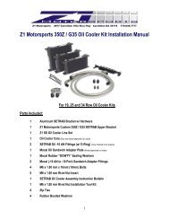
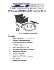
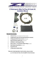
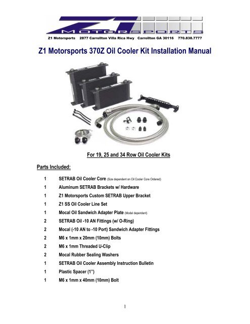
<strong>Z1</strong> <strong>Motorsports</strong> 2877 Carrollton Villa Rica Hwy Carrollton GA 30116 770.838.7777<strong>Z1</strong> <strong>Motorsports</strong> <strong>370Z</strong> <strong>Oil</strong> <strong>Cooler</strong> <strong>Kit</strong> <strong>Installation</strong> <strong>Manual</strong>For 19, 25 and 34 Row <strong>Oil</strong> <strong>Cooler</strong> <strong>Kit</strong>sParts Included:1 SETRAB <strong>Oil</strong> <strong>Cooler</strong> Core (Size dependent on <strong>Oil</strong> <strong>Cooler</strong> Core Ordered)1 Aluminum SETRAB Brackets w/ Hardware1 <strong>Z1</strong> <strong>Motorsports</strong> Custom SETRAB Upper Bracket1 <strong>Z1</strong> SS <strong>Oil</strong> <strong>Cooler</strong> Line Set1 Mocal <strong>Oil</strong> Sandwich Adapter Plate (Model dependent)2 SETRAB <strong>Oil</strong> -10 AN Fittings (w/ O-Ring)2 Mocal (-10 AN to -10 Port) Sandwich Adapter Fittings2 M6 x 1mm x 20mm (10mm) Bolts2 M6 x 1mm Threaded U-Clip2 Mocal Rubber Sealing Washers1 SETRAB <strong>Oil</strong> <strong>Cooler</strong> Assembly Instruction Bulletin1 Plastic Spacer (1”)1 M6 x 1mm x 40mm (10mm) Bolt1
Additional Parts:1 Quart (1 Liter) Engine <strong>Oil</strong> (Not Included)2 Additional Zip TiesTools Required:• Assorted Metric Wrenches (10mm – 19mm) • Assorted Metric Sockets (10mm – 19mm)• Assorted Metric Allen Head Wrenches• Ratchet• Assorted Screw Drivers• Pliers• Floor Jack • Jack Stands (Minimum of 2)• Tire removal tools• Torque Wrench• Funnel• Drill• Assorted Drill Bits! Space Intentionally Left Blank – Continue to the following page !2
<strong>Installation</strong>:WARNING!: Extreme caution should be taken when performing ANY maintenance or performance upgrades to yourvehicle. Please observe and abide by any Warning or Caution labels placed on the various components and tools usedwhen servicing your vehicle. If you have any questions regarding the installation or the various components includedwith the <strong>Z1</strong> <strong>Motorsports</strong> <strong>370Z</strong> <strong>Oil</strong> <strong>Cooler</strong> <strong>Kit</strong>, consult with a Professional Mechanic or contact <strong>Z1</strong> <strong>Motorsports</strong> for moreinformation.<strong>Installation</strong> Note #1:It is recommended that you perform the <strong>Z1</strong> <strong>Motorsports</strong> <strong>370Z</strong> <strong>Oil</strong> <strong>Cooler</strong> <strong>Kit</strong> installation at a scheduled interval whenyour vehicle requires an <strong>Oil</strong> Change. This due to the fact that the <strong>Oil</strong> Filter must be removed and that some Engine <strong>Oil</strong>will be lost in order to properly install the kit.*BEFORE YOU BEGIN!Remove all contents from the <strong>Z1</strong> <strong>Motorsports</strong> <strong>370Z</strong> <strong>Oil</strong> <strong>Cooler</strong> <strong>Kit</strong> and verify that ALL necessaryhardware is present.1. Apply the Parking Brake2. Properly raise and support your <strong>370Z</strong> using jack stands and the proper jacking pointson your vehicle’s chassis (Refer to vehicle’s Owner’s <strong>Manual</strong>)3. Disconnect the NEGATIVE (--) Battery Terminal4. Raise the vehicle’s Hood5. Remove Front Passenger Side Wheel6. Remove both the Lower Engine Splash Shield and the Passenger Side Inner FenderLiner. Refer to the images below for the exact location of the fasteners:a. Remove the following fasters, high lighted below. Fasters will be an assortmentof 10mm screws and Plastic Panel Clips. Use a flat blade screw driver to gentlypry the pop clips up.3
. Do not discard the small plastic panel shown here. It will be reinstalled later.c. Be sure to remove these two plastic panel clips. The one shown in the image belowon the Left will be exposed only after the lower engine shroud is removed. There isalso a plastic panel clip (not shown) at the very top of the fender liner that will alsoneed to be removed.4
7. Remove the Front Fascia Radiator Air Guide. This is done be using a flat blade screwdriver and gently popping out the center section of the 7 Plastic Pop Clips located underthe hood. The air guide will simply slide up and out from beneath the front fascia. Referto the image below for the location of the plastic pop clips.8. You will also need to remove the 7 additional Plastic Pop Clips securing the front fascia.Refer to the image below for the location of the plastic pop clips.9. Remove the two 10mm Plastic Screws5
10. Gripping the sides of fascia (circled below) pull the fascia towards you. This part of thefascia snaps in place and will pop loose when a limited amount of force is applied.Once free, carefully remove the fascia from the chassis and set aside.10 (continued). You should see something similar to the image below.<strong>Installation</strong> Note #2:Some individuals find that removing the Front Aluminum Crash Bar and Foam Reinforcement pad eases in theinstallation of the <strong>370Z</strong> <strong>Oil</strong> <strong>Cooler</strong> <strong>Kit</strong>s. This is not necessary.11. Assemble the SETRAB <strong>Oil</strong> <strong>Cooler</strong> Assembly using the supplied hardware and bracketsby following the instructions below:6
Locate the following parts:1 SETRAB <strong>Oil</strong> <strong>Cooler</strong> Core (Size dependent on <strong>Oil</strong> <strong>Cooler</strong> Core Ordered)1 Aluminum SETRAB Brackets w/ Hardware1 <strong>Z1</strong> <strong>Motorsports</strong> Custom SETRAB Upper Bracketa. Using the Aluminum SETRAB Bracket and it supplied hardware. Attach thebracket to the bottom of the oil cooler (opposite of the end with the fittings). Therotation of the bracket does not matter. The core can be rotated depending oninstallation preferences. Refer to the image below:b. Locate the <strong>Z1</strong> <strong>Motorsports</strong> Custom Upper Bracket w/ Hardware (All hardwareshould be assembled together for shipping purposes).7
c. Referring to the images below, you will attach the bracket to the top left handcorner of the SETRAB <strong>Oil</strong> <strong>Cooler</strong> Core.<strong>Installation</strong> Note #3:Since the core’s position is reversible, it is recommended that the oil cooler core be positioned as close to the A/CCondenser as possible. The <strong>Z1</strong> <strong>Motorsports</strong> Custom Upper Bracket can only be installed with the core in this position.Installatoin Note #3 (Continued):Refer to the image below for the exact position of the oil cooler brackets. This configuration isrecommended for all 370z/G37’s equipped with either the STILLEN GEN III Intake or a ForcedInduction Setup. Some modifications or reversal of the core support will be necessary wheninstalling an oil cooler core onto a 370z with the NISMO Brace <strong>Kit</strong> (Nissan Part # E4420-1EK000).d. Locate the two supplied M6 x 1mm Threaded U-Clips (x2) and two M6 x 1mm x20mm (10mm) Bolts [These should be threaded into one another for shippingpurposes].e. Slide the two Threaded U-Clips onto the core support as shown below. You willbe using the two blank spots on the Driver side of the core support (lower).8
f. You can now, temporarily position the oil cooler core/bracket assembly on thecore support of the vehicle. Using the two M6-1.00 bolts, secure the coresupport to the chassis, but DO NOT TIGHTEN DOWN ANY BOLTS.g. Position the oil cooler core so that the upper bracket’s unused sits just behindthe center core support brace (Vertical steel brace that should be sitting just tothe left of the oil cooler).h. With the core in place, you will now need to mark the location of the hole thatwill be used to attach the Upper <strong>Oil</strong> <strong>Cooler</strong> Core Bracket to the chassis. Thishole does not exist from the factory and will need to be drilled. Customers whohave purchased 19 and 25 row oil cooler kits can skip this step if they choose(not recommended), all customers who have purchased the 34 row oil cooler kitMUST install this bracket. The oil cooler core will be allowed to move too muchwithout the upper bracket and could possibly damage the fiberglass coresupport or A/C Condenser.9
<strong>Installation</strong> note #3Place a thin piece of wood between the vertical steel brace and the A/C Condenser core to prevent any accidentaldamage to the condenser itself while drilling. Remember the saying…”Measure twice and drill once!”.i. With the center brace drilled. Remove the oil cooler core from the vehicle.j. Locate the two SETRAB <strong>Oil</strong> <strong>Cooler</strong> Core Fittings. (These will be the only 2 loosefittings supplied with the kit. DO NOT remove the fittings from the oil sandwich plate tocomplete this step!!)k. Using a suitable lubricant, apply a thin layer of lubricant to the threads of thefitting and O-Rings. Only install ONE fitting at this time.l. Using Fresh Engine <strong>Oil</strong>, it is HIGHLY recommended that oil cooler core be filledcompletely. This will prevent a dry start scenario and will help prime the oilcooler FASTER!m. With the oil cooler filled, you may now install the second SETRAB Fitting to theoil cooler core.12. Again using the supplied bolts, attach the SETRAB <strong>Oil</strong> <strong>Cooler</strong> Assembly to the vehicle’score support. Be sure to tighten all three 10mm bolts. Ensure that there is nointerference with the A/C Condenser Lines, intake filters (If using the Stillen GEN IIIIntake) or other hardware.13. Locate the <strong>Z1</strong> <strong>Motorsports</strong> SS Line Set.a. Attach the oil cooler lines in the following pattern:i. Long Hose – Attach the 90° Fitting to the Driver Side SETRAB Fitting onthe <strong>Oil</strong> <strong>Cooler</strong> Core.ii. Short Hose - Attach the 90° Fitting to the Passenger Side SETRABFitting on the <strong>Oil</strong> <strong>Cooler</strong> Core.* Failure to attach the <strong>Oil</strong> <strong>Cooler</strong> Lines as listed above may result in insufficient line length in later steps. In addition,customers who choose the Pre-Wrapped Option will have the protective wrapping located in the wrong position.10
. Route the Line Set across the front of the vehicle. You may have to route thelines around aftermarket parts that have been installed.For example:The image below shows that the lines are routed in FRONT of the Passenger Side STILLEN GEN III Intake Filters. Thisis acceptable since the front fascia does not allow air to pass through this area anyway. This also positions the linesout of the way and in an ideal location for later routing steps.<strong>Installation</strong> note #4:The use of Zip Ties is suggested in order to keep the SS Line sets neat and pulled away from sharp, abrasive edges.c. You will now need to remove the plastic Air Deflector Located on the Passengerside of the fascia. This Panel will slide right off.d. Once removed, you will need to trim away the illustrated portion below. This willallow for adequate room for line routing in later steps.e. Re-install the modified air deflector panel back onto the chassis.11
f. Route the ends of the <strong>Oil</strong> <strong>Cooler</strong> Line set thru the opening between the CoreSupport and Windshield Washer Bottle. This allows the lines to rout neatlyalong the frame rails.<strong>Installation</strong> Note #5:You may need to loosen and/or unbolt the Windshield Washer Bottle to aid in routing the lines. Additionally, route thefittings one at a time. This will allow the lines to pass thru much easier.g. Locate the supplied 1” Plastic Spacer and associated Bolt.h. Unbolt the bracket securing the power steering cooler lines to the passengerside frame rail.i. Carefully route the lines between the power steering cooler lines and the framerail.j. Insert the 1” Spacer in between the bracket and the frame rail and reattach usingthe supplied bolt. Refer to the following image below:12
k. Referring to the following image, route the lines through the opening betweenthe passenger side frame rail and the front subframe.14. If you are planning on changing the engine oil during the installation of the <strong>Z1</strong><strong>Motorsports</strong> <strong>Oil</strong> <strong>Cooler</strong> <strong>Kit</strong>, remove Engine <strong>Oil</strong> Drain Plug and drain the engine oil. Ifyou are not planning on performing this step, continue to STEP #14.15. Remove the Engine <strong>Oil</strong> Filter.16. Locate the supplied Mocal Sandwich Adapter. This unit should already have the two(-10AN to -10 Port) Fittings and the two rubber sealing washers installed. Be sure toproperly tighten these fittings before continuing.17. Position the Mocal Sandwich Adapter with the large rubber o-ring facing the engine. DONOT INSTALL YET!13
18. Attach the two <strong>Oil</strong> <strong>Cooler</strong> Line Fittings to the Mocal <strong>Oil</strong> Sandwich Plate.19. Place the <strong>Oil</strong> Sandwich Plate assembly onto the engine. You will need to rotate thesandwich plate so that the 90° fitting is centered between the Alternator and the MotorMount. This is will result in the <strong>Oil</strong> Sandwich plate being rotated to about the 10’o’clockposition.20. With the Sandwich Plate in place and oriented properly. Angle the fittings so that theyclear any and all brackets, etc. Tighten the fittings as best as possible. Use Zip Ties tosecure the lines together.21. Remove the <strong>Oil</strong> Sandwich Plate assembly carefully. Be careful not to disturb the angleof the fittings. Tighten down the fittings.22. Re-install the <strong>Oil</strong> Sandwich Plate Adapter and securing bolt. Tighten down theSandwich Adapter bolt, securing the Mocal Sandwich Adapter to the engine in theproper orientation listed above.23. Install the Engine <strong>Oil</strong> Filter (New preferably).24. Refill the engine with oil.25. Crank the engine and inspect for any leaks.26. Re-install the previously removed Hardware, Fascia and Inner Fender Liners. Wheninstalling the various pieces for the Passenger Side Inner Fender Liners. Be sure thatthe <strong>Oil</strong> <strong>Cooler</strong> Lines are routed neatly behind the panels so that they DO NOT bulge out.This can (and will) eventually break the plastic pop clips, causing the panel to comeloose.27. Perform a final test drive of the vehicle.BE SURE TO CHECK THE ENGINE OIL LEVEL AFTER TEST DRIVING!14
For further information and MORE full color pictures and installationsuggestions, follow the installation link on the <strong>Z1</strong> <strong>Motorsports</strong> <strong>370Z</strong> <strong>Oil</strong><strong>Cooler</strong> <strong>Kit</strong> product page at <strong>Z1</strong><strong>Motorsports</strong>.comNOTES:15