Z1 350Z G35 Oil Cooler Kit Installation Manual - Z1Motorsports.com
Z1 350Z G35 Oil Cooler Kit Installation Manual - Z1Motorsports.com
Z1 350Z G35 Oil Cooler Kit Installation Manual - Z1Motorsports.com
- No tags were found...

Create successful ePaper yourself
Turn your PDF publications into a flip-book with our unique Google optimized e-Paper software.
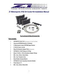
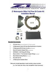
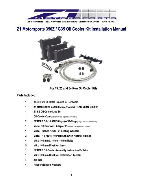
<strong>Z1</strong> Motorsports 2877 Carrollton Villa Rica Hwy Carrollton GA 30116 770.838.7777<strong>Z1</strong> Motorsports <strong>350Z</strong> / <strong>G35</strong> <strong>Oil</strong> <strong>Cooler</strong> <strong>Kit</strong> <strong>Installation</strong> <strong>Manual</strong>For 19, 25 and 34 Row <strong>Oil</strong> <strong>Cooler</strong> <strong>Kit</strong>sParts Included:1 Aluminum SETRAB Bracket w/ Hardware1 <strong>Z1</strong> Motorsports Custom <strong>350Z</strong> / <strong>G35</strong> SETRAB Upper Bracket1 <strong>Z1</strong> SS <strong>Oil</strong> <strong>Cooler</strong> Line Set1 <strong>Oil</strong> <strong>Cooler</strong> Core (Size and Model dependent on order)2 SETRAB <strong>Oil</strong> -10 AN Fittings (w/ O-Ring) (Only if Setrab Core ordered)1 Mocal <strong>Oil</strong> Sandwich Adapter Plate (Model dependent on order)1 Mocal Rubber “DOWTY” Sealing Washers2 Mocal (-10 AN to -10 Port) Sandwich Adapter Fittings4 M6 x 1.00 mm x 16mm (10mm) Bolts5 M6 x 1.00 mm Rivet Nut Insert1 SETRAB <strong>Oil</strong> <strong>Cooler</strong> Assembly Instruction Bulletin1 M6 x 1.00 mm Rivet Nut <strong>Installation</strong> Tool <strong>Kit</strong>4 Zip Ties4 Rubber Bonded Washers1
Additional Parts Re<strong>com</strong>mended:Additional Quart (1 Liter) of Engine <strong>Oil</strong> (Not Included)(1 QT (19 & 25 Row <strong>Kit</strong>s ONLY); 2 QTS Engine <strong>Oil</strong> (34 Row <strong>Kit</strong>s ONLY!)Additional Zip TiesTools Required:• Assorted Metric Wrenches (10mm – 19mm) • Assorted Metric Sockets (10mm – 19mm)• Assorted Metric Allen Head Wrenches• Ratchet• Assorted Screw Drivers• Pliers• Floor Jack • Jack Stands (Minimum of 2)• Tire removal tools• Torque Wrench• <strong>Oil</strong> Funnel• Drill (Corded or Cordless)• Assorted Drill Bits! Space Intentionally Left Blank – Continue to the following page !2
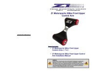
<strong>Installation</strong>:WARNING!: Extreme caution should be taken when performing ANY maintenance or performance upgrades to your vehicle. Please observe andabide by any and all Warning or Caution labels placed on the various <strong>com</strong>ponents and tools used when servicing your vehicle. If you have anyquestions regarding the installation or the various <strong>com</strong>ponents included with the <strong>Z1</strong> Motorsports <strong>350Z</strong>/<strong>G35</strong> <strong>Oil</strong> <strong>Cooler</strong> <strong>Kit</strong>, consult with a ProfessionalMechanic or contact <strong>Z1</strong> Motorsports for more information.<strong>Installation</strong> Note #1:It is re<strong>com</strong>mended that you perform the <strong>Z1</strong> Motorsports <strong>350Z</strong>/<strong>G35</strong> <strong>Oil</strong> <strong>Cooler</strong> <strong>Kit</strong> installation at a scheduled interval when your vehicle requires an <strong>Oil</strong>Change. This due to the fact that the <strong>Oil</strong> Filter must be removed and that some Engine <strong>Oil</strong> will be lost in order to properly install the kit.** BEFORE YOU BEGIN! **Remove all contents from the <strong>Z1</strong> Motorsports <strong>350Z</strong>/<strong>G35</strong> <strong>Oil</strong> <strong>Cooler</strong> <strong>Kit</strong> and verify that ALL necessary hardware is present.This is critical to prevent any loss in time or usage of your vehicle in the event that a part is either damaged or missing.1. Apply the Parking Brake2. Properly raise and support your Z / G using jack stands and the proper jacking points on your vehicle’s chassis(Refer to vehicle’s Owner’s <strong>Manual</strong>)3. Raise the vehicle’s Hood4. Disconnect the NEGATIVE (--) Battery Terminal<strong>Installation</strong> Note #2:Removal of the Front Passenger Side Wheel is suggested to ease in the removal of the Passenger Side Inner Fender Liner and for routing the -10AN <strong>Oil</strong> <strong>Cooler</strong> Lines. These tasks can however be achieved without removal of the wheel by simply turning the wheel each time access is needed toeither side.5. Remove both the Lower Engine Splash Shield and the Passenger Side Inner Fender Liner. Refer to theimages below for the exact location of the fasteners:6. Remove the fasteners securing the front fascia and Grille (<strong>G35</strong> only!). This is done by using a flat blade screwdriver and gently popping out the center section of the Plastic Pop Clips located under the hood.3
NOTE: On <strong>G35</strong> models, there are two additional “push-in” type fasteners attached to the grille that secure the grille to the fascia. Light pulling force will need to be applied in order toremove the grille. OEM or aftermarket Urethane fascias can be pried forward slightly in order to collapse the fasteners in order to remove the grille.2003 – 2009 Nissan <strong>350Z</strong> 2002 – 2006 Infiniti <strong>G35</strong> CoupeRemove the four 10mm Plastic Screws located in the corners of fascia, just behind the front fender liners (Refer toARROWS above). These are accessible by reaching into the fascia thru the fender wells or from beneath thevehicle following the removal of the fender liners.Gripping the sides of fascia, pull the ends of the fascia downward. A plastic alignment tab is located on each sideof the fascia and is designed to align it with the fenders during assembly. Once free, carefully remove the fasciafrom the chassis and set aside.<strong>Installation</strong> Note #3:When removing the fascia, remove one side at a time. When doing so, be extremely careful NOT to allow the fascia to rub against the fenders. Ifallowed to do so, damage to the painted surfaces will result.Remove the Foam Bumper Reinforcement Bar and Aluminum Crash Bar. Four 12mm bolts and Four 12mm Nutsare used to secure the crash bar onto the chassis.4
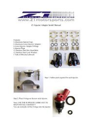
7. Assemble the SETRAB <strong>Oil</strong> <strong>Cooler</strong> Assembly using the supplied hardware and brackets by following theinstructions below:Locate the following parts:1 SETRAB <strong>Oil</strong> <strong>Cooler</strong> Core (Size dependent on <strong>Oil</strong> <strong>Cooler</strong> Core Ordered)1 Aluminum SETRAB Brackets w/ Hardware1 <strong>Z1</strong> Custom Upper <strong>Oil</strong> <strong>Cooler</strong> Bracketa. Using the Aluminum SETRAB Bracket and it supplied hardware. Attach the bracket to the bottom of the oilcooler (opposite of the end with the fittings). The rotation of the bracket does not matter. Refer to theimage below:5
. To install the <strong>Z1</strong> Custom Upper Bracket, assemble the bracket to the core as shown below. Please notethat the mounting flange on the Setrab Core MUST be laying flat as shown in the image in 7a. In thisposition, the upper bracket will be affixed to the left side of the oil cooler core.Tighten thesebolts ONLY!!DO NOT Tightenthese bolts yet!!c. Locate the four supplied M6 x 1.00mm Rivet Nuts, M6 Threaded Rivet Nut Tool and three M6 x 1mm(10mm) Bolts.d. Carefully mark and drill two holes (using a 5/16” Drill Bit) in the core support (along the area indicatedbelow). A few things to note about drilling into the fiberglass core support are:• Be cautious of the fact that the back side of the fiberglass core support IS NOT FLAT. For addedstrength, there are diagonal braces formed into the fiberglass. The holes required must be drilled inbetween the diagonal braces. This can be verified be looking at the backside of the core support.• The <strong>Oil</strong> <strong>Cooler</strong> Core should be positioned as close to center of the driver side core support opening aspossible.• Make sure that the oil cooler core, when mounted, will be level in relation to the radiator. Use theradiator cross tubes as a visual reference.Nissan <strong>350Z</strong>Infiniti <strong>G35</strong>Attach the <strong>Z1</strong> Custom Upper <strong>Oil</strong><strong>Cooler</strong> Bracket in this location. **Drill & mount theSetrab Bracket in thisarea.6Drill & mount theSetrab Bracket in thisarea.
e. Following the instructions supplied with the M6 Threaded Rivet Nut Tool, set the M6 Rivet nuts until theyhave fully seated against the backside of the fiberglass core support and DO NOT free spin. In the eventthat a M6 rivet nut is damaged during the installation, a spare is included in the kit for this very reason.f. Due to the fact that the core support is not perfectly flat, the supplied Setrab <strong>Oil</strong> <strong>Cooler</strong> Core Bracket willnot bolt directly to the core support. Locate the supplied Rubber Bonded washers included in the kit. Useone washer per bolt behind the bracket with the rubber facing the core support. This should supply enoughclearance so that the core is mounted parallel to the radiator / condenser.7
g. To mount the <strong>Z1</strong> Custom Upper <strong>Oil</strong> <strong>Cooler</strong> Bracket, refer to the following vehicle specific notes:Infiniti <strong>G35</strong> – The Core Support has a threaded M6 Rivet Nut already installed from the factory in the spotindicated by the LARGE Arrow above. Use one of the supplied M6 bolts to secure theupper bracket to the core support.Nissan <strong>350Z</strong> – A custom mounting provision will need to be created following the sameprocedures as discussed in steps 7c - 7e. Once the holes have been marked, drill theappropriate holes using a 5/16” drill bit.To adjust the arm, simply loosen the three 10mm bolts and allow movement. Depending on the applicationand core size, the mid-arm may need to be unbolted and reattached in order to use the middle adjustmentslot.h. Locate the two SETRAB <strong>Oil</strong> <strong>Cooler</strong> Core Fittings. (These will be the only 2 loose fittings supplied with the kit. DO NOTremove the fittings from the oil sandwich plate to <strong>com</strong>plete this step!!)i. Using a suitable lubricant, apply a thin layer of lubricant to the threads of the fitting and O-Rings. Onlyinstall ONE fitting at this time.j. Using Fresh Engine <strong>Oil</strong>, it is HIGHLY re<strong>com</strong>mended that oil cooler core be pre-filled <strong>com</strong>pletely beforemoving forward in the installation. This will prevent a dry start scenario and will help prime the oil coolerFASTER during the initial start-up!k. With the oil cooler filled, you may now install the second SETRAB Fitting to the oil cooler core.8. Locate the <strong>Z1</strong> Motorsports SS Line Set.a. Attach the oil cooler lines in the following pattern:- Long Hose – Attach the 90° Fitting to the Driver Side SETRAB Fitting on the <strong>Oil</strong> <strong>Cooler</strong> Core.- Short Hose - Attach the 90° Fitting to the Passenger Side SETRAB Fitting on the <strong>Oil</strong> <strong>Cooler</strong> Core.* Failure to attach the <strong>Oil</strong> <strong>Cooler</strong> Lines as listed above may result in insufficient line length in later steps. In addition, customers whochoose the Pre-Wrapped Option will have the protective wrapping located in the wrong position.b. Route the Line Set across the front of the vehicle. You may have to route the lines around aftermarketparts that have been installed.<strong>Installation</strong> note #4:The use of Zip Ties is suggested in order to keep the SS Line sets neat and pulled away from sharp, abrasive edges.8
c. Referring to the following image, route the lines through the opening between the passenger side frame railand the front subframe.9. If you are planning on changing the engine oil during the installation of the <strong>Z1</strong> Motorsports <strong>Oil</strong> <strong>Cooler</strong> <strong>Kit</strong>,remove Engine <strong>Oil</strong> Drain Plug and drain the engine oil. If you are not planning on performing this step, continueto STEP #16.10. Remove the Engine <strong>Oil</strong> Filter.11. Locate the supplied Mocal Sandwich Adapter. This unit should already have the two(-10AN to -10 Port) Fittings and the two rubber sealing washers installed. Be sure to properly tighten thesefittings before continuing.12. Position the Mocal Sandwich Adapter with the large rubber o-ring facing the engine. DO NOT INSTALL YET!13. Attach the two -10 AN <strong>Oil</strong> <strong>Cooler</strong> Lines to the Mocal <strong>Oil</strong> Sandwich Plate.14. Place the <strong>Oil</strong> Sandwich Plate assembly onto the engine. You will need to rotate the sandwich plate so that the180° fittings are centered between the Alternator and the Motor Mount (Refer to the image below). This is willresult in the <strong>Oil</strong> Sandwich plate being rotated to about the 10’o’clock position.9
15. With the Sandwich Plate in place and oriented properly. Angle the fittings so that they clear any and allbrackets and create a smooth bend, applying the least amount of stress on the -10 SS lines as possible.Tighten the fittings as best as possible. Use Zip Ties to secure the lines together.16. Remove the <strong>Oil</strong> Sandwich Plate assembly carefully. Be careful not to disturb the angle of the fittings. Onceremoved, tighten down the fittings.17. Re-install the <strong>Oil</strong> Sandwich Plate Adapter and securing bolt. Tighten down the Sandwich Adapter bolt andtorque it to 25 ft/lbs. This will secure the Mocal Sandwich Adapter to the engine in the proper orientation listedabove.18. Install the Engine <strong>Oil</strong> Filter (New preferably).19. Refill the engine with oil.20. Crank the engine and inspect for any leaks.21. Re-install the previously removed Hardware, Fascia and Inner Fender Liners. When installing the variouspieces for the Passenger Side Inner Fender Liners. Be sure that the <strong>Oil</strong> <strong>Cooler</strong> Lines are routed neatly behindthe panels so that they DO NOT bulge out. This can (and will) eventually break the plastic pop clips, causingthe panel to <strong>com</strong>e loose.22. Perform a final test drive of the vehicle.BE SURE TO CHECK THE ENGINE OIL LEVEL AFTER TEST DRIVING!For further information and MORE full color pictures and installation suggestions, follow theinstallation link on the <strong>Z1</strong> Motorsports <strong>350Z</strong>/<strong>G35</strong> <strong>Oil</strong> <strong>Cooler</strong> <strong>Kit</strong> product page at<strong>Z1</strong>Motorsports.<strong>com</strong>10