pdf, 3.8 MB
pdf, 3.8 MB
pdf, 3.8 MB

Create successful ePaper yourself
Turn your PDF publications into a flip-book with our unique Google optimized e-Paper software.
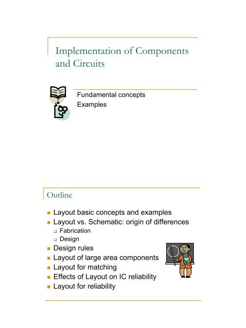
Layouts• Digital logic: automatic place & route,use of standard cells• Analog & High Performance: aidedmanual design• Components with multiple physicalimplementations Resistors Capacitors Bipolar transistors Power componentsExample of components: transistorsSingle-gate NMOS, 0.35 µmMultiple-gate NMOS, 0.35 µmVertical NPN BJT, 0.35 µmLateral BJT, 0.35 µm
Example of components: passives• N Diffusion resistor • Polysilicon resistor• Polysilicon capacitorP-cells• NMOS transistor • Polysilicon capacitor
Designing a layout: CAD Tools• Layout design aids in nowadays CAD Tools: Library of components’ layouts (Design Kit) Parameterized layouts Automatic layout generation (Place & route) Layout vs. Schematic Rules checking Extractor and layout simulation• Is the proposed layout a good layout?Designing a layout: CAD Tools• A good layout must be: Ease manufacturability (increase yield) Robust to variations Robust to gradients (matching) Robust against perturbations Robust against other undesired phenomena
Lithographyfrom Chiang, Kawa, “Design and Manufacturabilityand Yield for Nano-Scale CMOS”, Springer 2007Illuminator: can be Krypton Floride (KrF, λ=248 nm), Argon Floride(ArF, λ=193 nm), Fluorine (F2, λ=157 nm).Condenser Lens: focuses light on 4x (or 5x) maskPhotomask: made of fused quartz (aka. fused silica)Projection lens: focuses light on wafercharacterized by its numerical aperture NALithographyfrom Chiang, Kawa, “Design and Manufacturabilityand Yield for Nano-Scale CMOS”, Springer 2007Definition of numerical aperture NANA = n⋅sinαwhere n is a diffraction index:1 for air∼1.5 for water, oilsRayleigh’s equations:λλresolution = k1depth of focus ( DOF)= k2 NANA2where k 1 , k 2 depend on the quality of the photolithography system(typ. k 1 ∼ 0,25 – 0,7, k 2 ∼ 0,5)
Lithography• Example: which is the critical dimension that can be achieved withλ=248 nm?Reasonable NA for air is 0,8Guess k 1 =0,4248nmresolution = 0,4 = 124nm0,8• Example: which is the critical dimension that can be achieved withλ=193 nm?Reasonable NA for air is 0,8Guess k 1 =0,3193nmresolution = 0,3 = 72nm0,8Lithography• 436 nm: used down to 3 µm technologies• 365 nm: used down to 0,6 µm technologies• 248 nm: used down to 130 nm technologies• 193 nm in air (dry lithography)Used in technologies down to 90 nm(still in use for some layers in 65 nm, 45 nm...)
Lithography• 436 nm: used down to 3 µm technologies• 365 nm: used down to 0,6 µm technologies• 248 nm: used down to 130 nm technologies• 193 nm in air (dry lithography)• 157 nm: needs special lens materialsAbandoned definitively in 2005 (dueto technical difficulties associated with themask and photoresist materials for thiswavelength; also for the economical cost)Lithography• 436 nm: used down to 3 µm technologies• 365 nm: used down to 0,6 µm technologies• 248 nm: used down to 130 nm technologies• 193 nm in air (dry lithography)• 157 nm: needs special lens materials•EUV (λ=13 nm). New approach: mirrors, nolensesOptimistic forecast: ready for22 nm technology node(∼2011)
Lithography• 436 nm: used down to 3 µm technologies• 365 nm: used down to 0,6 µm technologies• 248 nm: used down to 130 nm technologies• 193 nm in air (dry lithography)• 193 nm in liquid (immersion lithography)Used in 65 nm, 45 nm, (32 nm)technology nodes (NA 1.1 → 1.3)Lithography• 193 nm in air (dry lithography)• 193 nm in liquid (immersion lithography)Double patterning: generate a singlelayer by using two masksDouble exposureUsed in 65 nm, 45 nm,technology nodesSpacer maskHeterogeneous mask
LithographyManufacturing: subwavelength gap103µmABOVE WAVELENGTHSilicon feature sizeSUB WAVELENGTH1436nm0.6µm365nm0.1Lithography Wavelength0.25µm193nm0.13µmtarget layout0.05µm1980 1990 2000 2008⇒ Increased difraction effects!from Massimo Conti, BCN 2006result
Differences between layout and Circuit (I)• Fabrication processlimitations Lateral diffusion Etching under protection Boundary dependentetching Three-dimensional effects Chemical MechanicalPolishing (CMP) Surface topographyDifferences between layout and Circuit (II)• Fabrication processlimitations Narrowing afterannealing Inherent grain variability Proximity effectsErrors and limitations Mask productions Mask alignmentOxide variations over a 20 Å nominal oxide thickness
Differences between layout and Circuit (III)• Absolute accuracy of physicalparametersControlled at technological levelSimulation: Process variation22σ ( β ) Aβ2= + S D2ββ WL2σ ( VA2VTT) = +WLS2VT2D2WLDfrom Massimo Conti, BCN 2006Differences between layout and Circuit (III)• Absolute accuracy of physicalparametersC = εdielectricL ⋅Wtoxlength Linterlayerdistance t ox2 2 22 2⎛ ε ⎞ ⎛dielectrict ⎞ox⎛ C ⎞ ⎛ L ⎞ ⎛ W ⎞⎜ ⎟ = ⎜ ⎟ + ⎜ ⎟ + ⎜ ⎟ + ⎜ ⎟⎝∆C⎠ ∆ε∆t ⎝∆L⎠ ⎝∆W⎠⎝ dielectric ⎠ ⎝ ox ⎠width W• oxide damage• impurities• temperature•stress• bias conditions• growth rate• grain size• etching inaccuracy• mask alignmentfrom Franco Maloberti, “Layout of Analog CMOS ICs”
Differences between layout and Circuit (IV)• Relative inaccuracies ofphysical parameters Gradients, local variations Compensated with suitablelayout techniquesCrystal orientationvariations Components required to belaid in a determinedorientationPressure gradientsThermal gradientsDifferences between layout and Circuit (IV)• Example: normalized draincurrent dispersions of 2MOSFETs for differentgeometries and distancesW=L= 0.5 µm d= 5µm W=L= 10 µm d= 5µmInaccuracy in absolute value,but matched devicesInaccuracy in absolute value,and mismatched devicesfrom Massimo Conti, BCN 2006W=L= 0.5 µm d= 100µmW=L= 10µm d= 100µm
Differences between layout and Circuit (V)• Parasitic coupling Capacitive coupling Couplings through the power supply Couplings through the substrate• Parasitic resistances Contacts InterconnectWhat you get is not what you draw!• Many of the systematic inaccuracies can beavoided through good layout style.• But designers must understand the limitationsand apply design techniques to mitigatethese effects.
Corrections performed by the foundry• Some manufacturingdistortions can bepredicted and fixedby introducingmodifications to themask OPC: OpticalProximity CorrectionFrom “Nano-CMOS Circuit and Physical Design”,Wong et al, IEEE PressCorrections performed by the foundryExamples ofcorrectionsautomaticallyintroduced by a OPCalgorithm to theshapes in the maskFrom “Nano-CMOS Circuit and PhysicalDesign”, Wong et al, IEEE Press
Corrections performed by the foundryThis top down SEMimage was takenwithout any OPC.The pullback overthe contact isclearly seenFrom Intel IrelandThis image of thesame structure wastaken with OPCimplemented on themask. Good contactcoverage can beseen.Design for manufacturability: design rules:Example: Poly 1
Example of design rules for POLY 1• PO.W.1a Minimum gate length of PMOS• PO.W-2a Minimum gate length of NMOS• PO.W.3 Minimum POLY1 width for interconnect• PO.S.1 Minimum POLY1 spacing• PO.C.1 Minimum POLY 1 to DIFF spacing• PO.C.2 Minimum DIFF extension of GATE• PO.O.1 Minimum POLY1 extension of GATEOptimized layouts:Bad layoutOptimized layoutInsufficient via openingEffective L larger than drawnEffective W larger than drawnFrom “Nano-CMOS Circuit and PhysicalDesign”, Wong et al, IEEE Press
Optimized layouts:Optimize efficiency of vias/contactsMaximize number of vias/contactsOptimized layoutAll transistors in the sameorientation• Better control of manufacturing• Easier lithography (mask)correctionsFrom “Nano-CMOS Circuit and PhysicalDesign”, Wong et al, IEEE PressOptimized layouts:Possible shortcircuit of nodes A andB due to diffussion flaring and maskmisalingmentPossible shortcircuit due topoly flaringPossible shortcircuit due todiffussion flaringFrom “Nano-CMOS Circuit and PhysicalDesign”, Wong et al, IEEE Press
Layout for matching• Devices with the sameorientationCurrent in the samedirection• Gradients increase withdistance• Same orientationtowards physicalgradientsDissipatingdeviceDevice 1Device 2DissipatingdeviceDevice 1Device 2T1T2T1T2Layout for matching• Interdigitated structuresMOS transistors M1 and M2Resistors R1 and R2
Layout for matching• Interdigitated structuresDifferent symmetry axes fortransistors A and BSame symmetry axis fortransistors A and Bfrom Franco Maloberti, “Layout of Analog CMOS ICs”Layout for matching• Common centroid:
Layout for matching: Common centroid• Coincidence Centroids of matched devices should coincide• Symmetry Array symmetric around both X and Y axis• Dispersion Segment of each device distributed throughoutthe array as uniformly as possible• Compactness Ideally: array should be squareLayout for matching: Common centroidfrom Franco Maloberti, “Layout of Analog CMOS ICs”
Layout for matching: Use of dummies• DummiesUse dummy devices to provide the same contour conditions. Ground dummies (do not let them float) Dummies can be full (shorted) devices, or part of them Beware of their parasitics!Layout for matching: Use of dummies• Reference cellUse multiple basic transistors instead of different sizes Same W, same orientation,
Design of large area components• MOS TransistorsMultiple gates to minimizeserial resistanceMultiple contacts to minimizeserial resistance No big contacts!!!“stacked” structures Lower parasitic capacitances Lower areaAnalogue applications Avoid minimum sizeAutomatically generated layoutsAMS, 0.35 microns, 10/0.35Design of large area components• ResistancesBended structuresDummy structures45 degrees (avoid nonlaminar current flow)Contacts Current in the samedirection Multiple contactsPiezoresistive effectResistor: 5K, 275x3 sq microns.Example of “good” and “bad” layout
Layout for matching: interconnects• CMP:Erosion effect: denser interconnects will have higher RFrom “Nano-CMOS Circuit and PhysicalDesign”, Wong et al, IEEE PressRules for matching• Same W and L: Vary M• CapacitorsMultiple M of a capacitance reference C R• Ms: Even (factors of 4!!)• Clean and balanced routingIR dropsParasitic capacitance and couplingsKelvin connections• Avoid minimum sizing and overlapping• Use dummy structures• Same spacing in interconnects
Layout Strategies for circuit reliability (I)• ElectromigrationElectromigration is the transport of material caused bythe gradual movement of the ions in a conductor due tothe momentum transfer between conducting electronsand diffusing metal atomsDependent on: Temperature Current density Conductor Shape MaterialLayout for reliability: Electromigration• Exist technological preventive measures Type of metal layer (Cu better than Al) Oxidation (better over field oxide) Use of protective overcoats• Width of interconnections: M µm/mA Typical M: between 1 and 0.5• Maximum current per contact and vias
Layout Strategies for circuit reliability (II)• Latch-up A latchup is the inadvertentcreation of a low-impedancepath between the powersupply rails of an electroniccomponent, triggering aparasitic device, which thenacts as a short circuit,leading to malfunctioning ofthe part and perhaps evenits destruction with theovercurrentLayout for reliability: Latch-up• Activation:If voltages higher than VDDIf voltages lower than GNDIf currents through the well/substrateI/O Circuitry more sensitive• Elimination of minority carriersGuard ringsBiased with low resistances• Reduce beta parasitic transistors. Reduce forwardbias resistance
Layout for reliability: Latch-up• Reduce forward bias resistance:Rules:Layout for reliability: Latch-up• I/O Circuitry more sensitiveXXXXI/Otransistorssurroundedby pick-upsand guardringsI/O and coretransistorsseparatedby guardrings
Layout Strategies for circuit reliability (III)• CMP Chemical MechanicalPolishing or ChemicalMechanical Planarization Removal any irregulartopography Surface within the depthof field of aphotolithography system.Layout for reliability: CMP• Example: MOSIS 0.25(TSMC)• Design rules:Minimum % coverage ofMetal layersPolysilicon layersCapacitor Layers
Layout for reliability: CMP2µ 2µ5µDummy patterns are distributedover the chip as uniformly aspossible in order to reach therequired coverage for eachmaterial (Metal 1, 2, 3, 4, 5, Poly 1and CTM (capacitor top metal) )All Metal Fill pattern(staked M1, M2, M3, M4 )Poly 1 Fill pattern asmetalLayout for reliability: CMP1. Orientation of dummy pattern should be perpendicular toprevious layer2. Top layer should have larger dummy patternExample: 4-metal technologyPattern for M1Pattern for M2 Pattern for M3 Pattern for M4 (top)
Layout for reliability: CMP• Patterns generated automatically by the foundry• User has masks to define areas that will NOT be filled with patterns(Ex: inductors, capacitors, test strcutures, etc)Example in a 0,18 µm technology:Layout for reliability: CMPExample of Transmission line inM7 with dummy metals below :Open question: How do dummymetal fills affect transmission linesand passives ?“A Bidirectional- and Multi-Drop-Transmission-Line Interconnect…”,IEEE JSSC April 2008
Layout for reliability: CMPProposal: slow-wave transmission lines-Low Q- Small area- Necessary grid fulfills metal coverageBorremans et al., “VCO design for 60 GHz applications usingdifferential shielded inductors in 0.13 µm CMOS”, RFIC’08Layout for reliability: CMP• Slots Act both as stressreleasers and tominimize dishing Slots in metals W>Value (tech. dependent) Possible library ofcomponents Corners Padsdishing
Layout Strategies for circuit reliability (IV)• Antenna Effects or Plasma-Induced damageThe "Antenna Rules" deal with process induced gate oxidedamage. Reactive ion-etching may induce charges toexposed polysilicon and metal structures. If thesestructures are connected to gates (and not to diffusion),they may develop potentials sufficiently large to causeFowler Nordheim current to flow through the thin oxideLayout for reliability: Antenna• Vulnerability depends on ratiobetween periphery/area oftrapping material to gate area• Fab. 1: Rules Poly and metallayers (including contacts) Max perimeter ratio of field polyto active poly Max perimeter ratio of floatingmetals to active poly Max drawn area of CO vs.Active PolyPoly and Metal ratio definition2ratio =[( L1+ W1)⋅ Z1]W 2⋅L2Contact and via ratio definitionContact(Via) arearatio =W 2⋅L2
Layout for reliability: Antenna• Fab. 2 Maximum floating (Poly,Metal) Edge area ratio toactive area ratio.• Use of “leakers” and metal jumpersLayout Strategies for circuit reliability (V)• ESDElectrostatic DischargeDamage in dielectrics due to IC manipulation (mainly gateoxide)
Layout for reliability: Analog PADDiodes and resistors for ESD protectionReverse diodes: Parasitic capacitance!!!Example of RF PAD without diodes
References• The art of Analog Layout, 2nd Edition. Alan Hastings. Ed. Prentice Hall• Nano-CMOS Circuit and Physical Design. B.P. Wong et al. Wiley-Interscience, IEEE Press• CMOS Circuit Design, Layout and Simulation. R. J. Baker. Wiley IEEEPress• Layout of Analog and Mixed Analog-Digital Circuits. Franco Maloberti.• http://www.wikipedia.org/