SWITCHMODE⢠Power Supply Reference Manual
SWITCHMODE⢠Power Supply Reference Manual
SWITCHMODE⢠Power Supply Reference Manual

You also want an ePaper? Increase the reach of your titles
YUMPU automatically turns print PDFs into web optimized ePapers that Google loves.
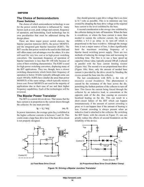
SMPSRMThe Choice of Semiconductors<strong>Power</strong> SwitchesThe choice of which semiconductor technology to usefor the power switch function is influenced by manyfactors such as cost, peak voltage and current, frequencyof operation, and heatsinking. Each technology has itsown peculiarities that must be addressed during thedesign phase.There are three major power switch choices: thebipolar junction transistor (BJT), the power MOSFET,and the integrated gate bipolar transistor (IGBT). TheBJT was the first power switch to be used in this field andstill offers many cost advantages over the others. It is alsostill used for very low cost or in high power switchingconverters. The maximum frequency of operation ofbipolar transistors is less than 80–100 kHz because ofsome of their switching characteristics. The IGBT is usedfor high power switching converters, displacing many ofthe BJT applications. They too, though, have a slowerswitching characteristic which limits their frequency ofoperation to below 30 kHz typically although some canreach 100 kHz. IGBTs have smaller die areas than powerMOSFETs of the same ratings, which typically means alower cost. <strong>Power</strong> MOSFETs are used in the majority ofapplications due to their ease of use and their higherfrequency capabilities. Each of the technologies will bereviewed.The Bipolar <strong>Power</strong> TransistorThe BJT is a current driven device. That means that thebase current is in proportion to the current drawn throughthe collector. So one must provide:IB IC hFE (eq. 8)In power transistors, the average gain (h FE ) exhibited atthe higher collector currents is between 5 and 20. Thiscould create a large base drive loss if the base drive circuitis not properly designed.One should generate a gate drive voltage that is as closeto 0.7 volts as possible. This is to minimize any losscreated by dropping the base drive voltage at the requiredbase current to the level exhibited by the base.A second consideration is the storage time exhibited bythe collector during its turn–off transition. When the baseis overdriven, or where the base current is more thanneeded to sustain the collector current, the collectorexhibits a 0.3–2 s delay in its turn–off which isproportional to the base overdrive. Although the storagetime is not a major source of loss, it does significantlylimit the maximum switching frequency of abipolar–based switching power supply. There are twomethods of reducing the storage time and increasing itsswitching time. The first is to use a base speed–upcapacitor whose value, typically around 100 pF, is placedin parallel with the base current limiting resistor(Figure 16a). The second is to use proportional base drive(Figure 16b). Here, only the amount of needed basecurrent is provided by the drive circuit by bleeding theexcess around the base into the collector.The last consideration with BJTs is the risk ofexcessive second breakdown. This phenomenon iscaused by the resistance of the base across the die,permitting the furthest portions of the collector to turn offlater. This forces the current being forced through thecollector by an inductive load, to concentrate at theopposite ends of the die, thus causing an excessivelocalized heating on the die. This can result in ashort–circuit failure of the BJT which can happeninstantaneously if the amount of current crowding isgreat, or it can happen later if the amount of heating isless. Current crowding is always present when aninductive load is attached to the collector. By switchingthe BJT faster, with the circuits in Figure 15, one cangreatly reduce the effects of second breakdown on thereliability of the device.V BBV BB100 pFControl IC100 pF+V BE–+V CE–Control IC<strong>Power</strong> Ground<strong>Power</strong> Ground(a) Fixed Base Drive Circuit(b) Proportional Base Drive Circuit (Baker Clamp)Figure 16. Driving a Bipolar Junction Transistorhttp://onsemi.com16