SWITCHMODE⢠Power Supply Reference Manual
SWITCHMODE⢠Power Supply Reference Manual
SWITCHMODE⢠Power Supply Reference Manual

Create successful ePaper yourself
Turn your PDF publications into a flip-book with our unique Google optimized e-Paper software.
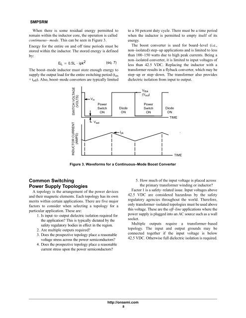
SMPSRMWhen there is some residual energy permitted toremain within the inductor core, the operation is calledcontinuous– mode. This can be seen in Figure 3.Energy for the entire on and off time periods must bestored within the inductor. The stored energy is definedby:EL 0.5L ipk 2 (eq. 7)The boost–mode inductor must store enough energy tosupply the output load for the entire switching period (t on+ t off ). Also, boost–mode converters are typically limitedto a 50 percent duty cycle. There must be a time periodwhen the inductor is permitted to empty itself of itsenergy.The boost converter is used for board–level (i.e.,non–isolated) step–up applications and is limited to lessthan 100–150 watts due to high peak currents. Being anon–isolated converter, it is limited to input voltages ofless than 42.5 VDC. Replacing the inductor with atransformer results in a flyback converter, which may bestep–up or step–down. The transformer also providesdielectric isolation from input to output.SWITCH VOLTAGE(VOLTS)V in<strong>Power</strong>SwitchONDiodeONV flbk(V out )<strong>Power</strong>SwitchONDiodeONTIMEINDUCTOR CURRENT(AMPS)V satI pkTIMEFigure 3. Waveforms for a Continuous–Mode Boost ConverterCommon Switching<strong>Power</strong> <strong>Supply</strong> TopologiesA topology is the arrangement of the power devicesand their magnetic elements. Each topology has its ownmerits within certain applications. There are five majorfactors to consider when selecting a topology for aparticular application. These are:1. Is input–to–output dielectric isolation required forthe application? This is typically dictated by thesafety regulatory bodies in effect in the region.2. Are multiple outputs required?3. Does the prospective topology place a reasonablevoltage stress across the power semiconductors?4. Does the prospective topology place a reasonablecurrent stress upon the power semiconductors?5. How much of the input voltage is placed acrossthe primary transformer winding or inductor?Factor 1 is a safety–related issue. Input voltages above42.5 VDC are considered hazardous by the safetyregulatory agencies throughout the world. Therefore,only transformer–isolated topologies must be used abovethis voltage. These are the off–line applications where thepower supply is plugged into an AC source such as a wallsocket.Multiple outputs require a transformer–basedtopology. The input and output grounds may beconnected together if the input voltage is below42.5 VDC. Otherwise full dielectric isolation is required.http://onsemi.com8