SWITCHMODE⢠Power Supply Reference Manual
SWITCHMODE⢠Power Supply Reference Manual
SWITCHMODE⢠Power Supply Reference Manual

You also want an ePaper? Increase the reach of your titles
YUMPU automatically turns print PDFs into web optimized ePapers that Google loves.
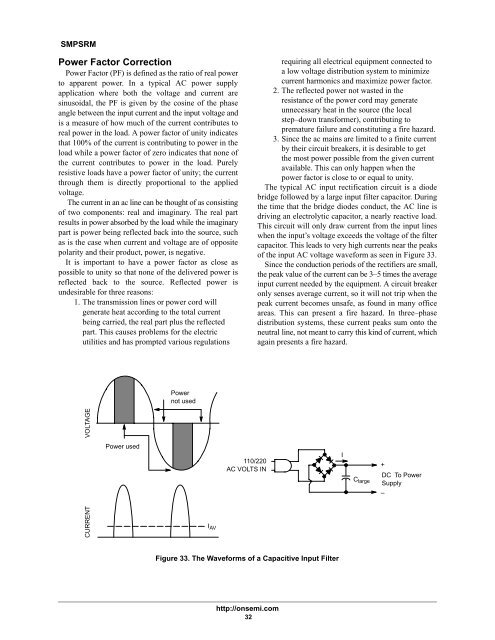
SMPSRM<strong>Power</strong> Factor Correction<strong>Power</strong> Factor (PF) is defined as the ratio of real powerto apparent power. In a typical AC power supplyapplication where both the voltage and current aresinusoidal, the PF is given by the cosine of the phaseangle between the input current and the input voltage andis a measure of how much of the current contributes toreal power in the load. A power factor of unity indicatesthat 100% of the current is contributing to power in theload while a power factor of zero indicates that none ofthe current contributes to power in the load. Purelyresistive loads have a power factor of unity; the currentthrough them is directly proportional to the appliedvoltage.The current in an ac line can be thought of as consistingof two components: real and imaginary. The real partresults in power absorbed by the load while the imaginarypart is power being reflected back into the source, suchas is the case when current and voltage are of oppositepolarity and their product, power, is negative.It is important to have a power factor as close aspossible to unity so that none of the delivered power isreflected back to the source. Reflected power isundesirable for three reasons:1. The transmission lines or power cord willgenerate heat according to the total currentbeing carried, the real part plus the reflectedpart. This causes problems for the electricutilities and has prompted various regulationsrequiring all electrical equipment connected toa low voltage distribution system to minimizecurrent harmonics and maximize power factor.2. The reflected power not wasted in theresistance of the power cord may generateunnecessary heat in the source (the localstep–down transformer), contributing topremature failure and constituting a fire hazard.3. Since the ac mains are limited to a finite currentby their circuit breakers, it is desirable to getthe most power possible from the given currentavailable. This can only happen when thepower factor is close to or equal to unity.The typical AC input rectification circuit is a diodebridge followed by a large input filter capacitor. Duringthe time that the bridge diodes conduct, the AC line isdriving an electrolytic capacitor, a nearly reactive load.This circuit will only draw current from the input lineswhen the input’s voltage exceeds the voltage of the filtercapacitor. This leads to very high currents near the peaksof the input AC voltage waveform as seen in Figure 33.Since the conduction periods of the rectifiers are small,the peak value of the current can be 3–5 times the averageinput current needed by the equipment. A circuit breakeronly senses average current, so it will not trip when thepeak current becomes unsafe, as found in many officeareas. This can present a fire hazard. In three–phasedistribution systems, these current peaks sum onto theneutral line, not meant to carry this kind of current, whichagain presents a fire hazard.<strong>Power</strong>not usedCURRENTVOLTAGE<strong>Power</strong> usedI110/220+AC VOLTS INDC To <strong>Power</strong>C large <strong>Supply</strong>–I AVFigure 33. The Waveforms of a Capacitive Input Filterhttp://onsemi.com32