SWITCHMODE⢠Power Supply Reference Manual
SWITCHMODE⢠Power Supply Reference Manual
SWITCHMODE⢠Power Supply Reference Manual

You also want an ePaper? Increase the reach of your titles
YUMPU automatically turns print PDFs into web optimized ePapers that Google loves.
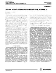
ÉÉ ÂÂÂÂÂÂÂÂÂÂÂÉÉÉÉÉÉÉÉSMPSRMThe grounds are extremely important to the properoperation of the switching power supply, since they formthe reference connections for the entire supply; eachground has its own unique set of signals which canadversely affect the operation of the supply if connectedimproperly.There are five distinct grounds within the typicalswitching power supply. Four of them form the returnpaths for the current loops described above. Theremaining ground is the low–level analog control groundwhich is critical for the proper operation of the supply.The grounds which are part of the major current loopsmust be connected together exactly as shown inFigure 21. Here again, the connecting point between thehigh–level AC grounds and the input or output groundsis at the negative terminal of the appropriate filtercapacitor (points A and B in Figures 21a and 21b). Noiseon the AC grounds can very easily escape into theenvironment if the grounds are not directly connected tothe negative terminal of the filter capacitor(s). Theanalog control ground must be connected to the pointwhere the control IC and associated circuitry mustmeasure key power parameters, such as AC or DCcurrent and the output voltage (point C in Figures 21a and21b). Here any noise introduced by large AC signalswithin the AC grounds will sum directly onto thelow–level control parameters and greatly affect theoperation of the supply. The purpose of connecting thecontrol ground to the lower side of the current sensingresistor or the output voltage resistor divider is to form a“Kelvin contact” where any common mode noise is notsensed by the control circuit. In short, follow the examplegiven by Figure 21 exactly as shown for best results.The last important factor in the PCB design is thelayout surrounding the AC voltage nodes. These are thedrain of the power MOSFET (or collector of a BJT) andthe anode of the output rectifier(s). These nodes cancapacitively couple into any trace on different layers ofthe PCB that run underneath the AC pad. In surfacemount designs, these nodes also need to be large enoughto provide heatsinking for the power switch or rectifier.This is at odds with the desire to keep the pad as small aspossible to discourage capacitive coupling to othertraces. One good compromise is to make all layers belowthe AC node identical to the AC node and connect themwith many vias (plated–through holes). This greatlyincreases the thermal mass of the pad for improvedheatsinking and locates any surrounding traces offlaterally where the coupling capacitance is much smaller.An example of this can be seen in Figure 22.Many times it is necessary to parallel filter capacitorsto reduce the amount of RMS ripple current eachcapacitor experiences. Close attention should be paid tothis layout. If the paralleled capacitors are in a line, thecapacitor closest to the source of the ripple current willoperate hotter than the others, shortening its operatinglife; the others will not see this level of AC current. Toensure that they will evenly share the ripple current,ideally, any paralleled capacitors should be laid out in aradially–symmetric manner around the current source,typically a rectifier or power switch.The PCB layout, if not done properly, can ruin a goodpaper design. It is important to follow these basicguidelines and monitor the layout every step of theprocess.<strong>Power</strong> DeviceViaPCB TopÉÉÉÉPlated–Thru HolePCB BottomÂÂÂÂÂÂÂÂÂÂÂ ÉÉFigure 22. Method for Minimizing AC Capacitive Coupling and Enhancing Heatsinkinghttp://onsemi.com23