SWITCHMODE⢠Power Supply Reference Manual
SWITCHMODE⢠Power Supply Reference Manual
SWITCHMODE⢠Power Supply Reference Manual

Create successful ePaper yourself
Turn your PDF publications into a flip-book with our unique Google optimized e-Paper software.
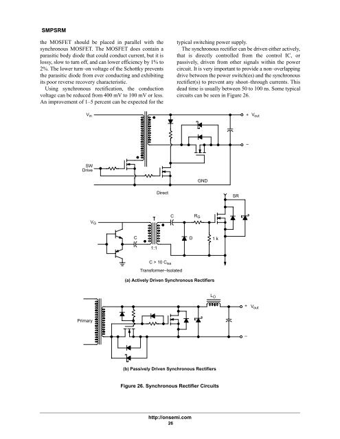
SMPSRMthe MOSFET should be placed in parallel with thesynchronous MOSFET. The MOSFET does contain aparasitic body diode that could conduct current, but it islossy, slow to turn off, and can lower efficiency by 1% to2%. The lower turn–on voltage of the Schottky preventsthe parasitic diode from ever conducting and exhibitingits poor reverse recovery characteristic.Using synchronous rectification, the conductionvoltage can be reduced from 400 mV to 100 mV or less.An improvement of 1–5 percent can be expected for thetypical switching power supply.The synchronous rectifier can be driven either actively,that is directly controlled from the control IC, orpassively, driven from other signals within the powercircuit. It is very important to provide a non–overlappingdrive between the power switch(es) and the synchronousrectifier(s) to prevent any shoot–through currents. Thisdead time is usually between 50 to 100 ns. Some typicalcircuits can be seen in Figure 26.V in+V out–SWDriveGNDDirectSRV GCR GCD1 k1:1C > 10 C issTransformer–Isolated(a) Actively Driven Synchronous RectifiersL O+V outPrimary–(b) Passively Driven Synchronous RectifiersFigure 26. Synchronous Rectifier Circuitshttp://onsemi.com26