A Balanced Short-Wave ReceiverA Description, by the Designer of the Best Receiver Submitted in <strong>Radio</strong><strong>Broadcast</strong>'s Recent Contest, of a Short-Wave Receiver That Won't Radiateshort-wave receiver described byTHE theauthor in the September, 1926, issue ofRADIO BROADCAST was an effort towardthe design of a short-wave receiver whichwould not radiate and interfere with othernear-by receivers. Although it had many desirablefeatures, it was not as sensitive as a standardshort-wave receiver. The receiver describedin this article is the result of further experimentsand calculations carried along thesame lines. If made carefully, it does not radiateat all and is, in the author's opinion, just assensitive as the ordinary carefully built shortwavereceiver. The improvement over the firstreceiver described is considerable; in fact, thereis no comparison between the two, both as tonon-radiating qualities and sensitivity.The receiver, as shown in the accompanyingpictures, was a model built up after the circuitwas conceived and not in its final form, since athorough job of shielding had not been donewhen the photographs were taken. Imperfectthough the photographed receiver was, it waspossible to copy New Zealand amateurs on asecond receiver while this incompleted one wasconnected to the same antenna and ground system and permitted to oscillate on the samefrequency as the distant station. No interferencewhatsoever was apparent from the oscillatingset during the reception of the NewZealand stations. The writer has never seenany other short-wave receiver which could approachthat mark for non-radiating qualitiesWhen listening to the same New Xealand stationon the balanced receiverdescribed here, the standardreceiver could notbe tuned to the samefrequency without absolutelyswampingeverything with itswhistling. In fact, itwould ruin any attemptto receive anything excepta local stationwhen it was oscillatingon the same frequencyas the received station.Capacity coupling tothe same antenna wasused by both receivers,one being the balancedand the other a standardReinartz receiver.The circuit of thebalanced receiver isshown in Fig. I, and, ascan be readily seen, isa form of Wheatstonebridge. It is absolutelynecessary to use someform of a bridge withthe antenna and groundacross zero potentialpoints of the oscillatingcircuit or circuits.In Fig. i. the midgetBy FRANK C.Amateur Station 6 AJFJONEScoupling condensers, Q and d, form the twocapacitive arms of the bridge and Li,Ca,Csand LjCiCr form the essential arms on theother side of the bridge. Both of these latterarms are tune.l simultaneously to the same frequency,i.e., that of the incoming frequency andplus or minus say 1000 cycles for heterodyningpurposes, and Ci and C2 are left set in a certainnlation to each other. Cs is a resultant capacityfrom the combination of Ci and the gridfilamentcapacity, C ?. The condensers Cs andQ are on the same shaft and should be exactlysimilar so that the two circuits will be tuned tothe same frequency or wavelength at any pointof the tuning scale. The tickler coils, L2 and L4,are coupled inductively to their respective coils,Li and LS, in the proper phase relation to causethe oscillatory currents in the bridge to justneutralize each other, or balance out. L? is coupledto Li so that the detector will oscillate, andLt is reversed with respect to direction of windingto La. Cj is a very small neutralizing typecondenser which is set to the same capacity asGi. This latter setting is easy to determine inpractice. Ce is simply a "throttle" condenserto control the amount of regeneration or oscillationin the detector circuit, such as is used inpractically all modern short-wave receivers.Thus the balanced receiver has one tuning controland one feed-back control, the latter beingadjusted only once or twice throughout the wholetuning range of the receiver. Simplicity and easeof tuning have been accomplished in this receiver.Now for some simple theory as to why the receiverdoes not radiate when properly balanced.The energy of the incoming signal at any oneinstant can be represented by the dotted arrows.This energy splits and part of itgoesthrough each coupling condenser, Ci and C;.The tuning circuits associated with LI and U,are tuned to the frequency of the desired incomingsignal energy and so offer an extremelyhigh impedance to this energy. This means thatmost of the signal energyisimpressed equallyacross the grid-filament capacity of the detectortube and the small capacitance C?. The actionthus far is the same as for any receiver. Theenergy component in the plate circuit of the detectorthrough the tickler coils L. and L, induceenergy in the coils Li and L3 respectively, thatin Li in a direction as indicated by the singleheadedsolid arrow, and in Ls in a direction asshown by the double-headed solid arrow. Thisis obtained by having the direction of the windingsof the coils in reverse directions. The energyinduced in Li adds to the incoming signal energyof the same frequency. and this continuous feedbackcauses the detector to oscillate. Unfortunately,part of this feed-back energy, as shownby the single solid arrows, splits at the top ofthe bridge, part of itgoing across the grid andthe rest through Ci to the antenna, which can,for our purposes, be represented as an inductance,resistance, and capacitance acrossthe points A and G, as shown in Fig. I.The energy induced in Ls, however, is in sucha direction as to be opposite to that inducedin Li in its effectacross the points A andG. The net effect in theantenna circuit is zerooutput from the receiver.Thus we have aone way circuit, theantenna gives energyto the detector but doesnot take any away.Since the circuitCiLsCv is tuned to thedesired frequency, as isalso LiC3Cs, these twoarms of the bridge offerhigh impedance to thefeed-back energy fromthe opposite tickler coilsrespectively, and mostof the energy finds itsway across the pointsA and G. The reactanceor impedance of theantenna circuit is comparativelylow so thatthe main components ofenergy are as shown bythe arrows. The minutequantities, in comparisonwith those shownthe arrows, can bebySHOWING THE DISPOSITION OF PARTS WITHIN THE CABINETautomatically eliminatedor compensated
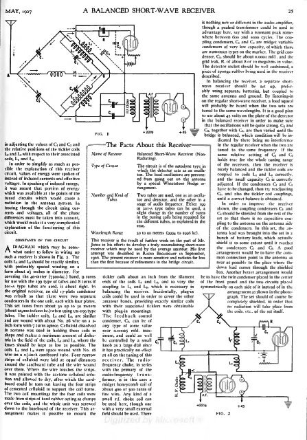
andMAY, <strong>1927</strong> A BALANCED SHORT-WAVE RECEIVER 25in adjusting the values of Ci and and C2the relative positions of the tickler coilsLj and L< with respect to their associatedcoils, Li and L3 .In order to simplify as much as possiblethe explanation of this receivercircuit, values of energy were spoken ofinstead of induced currents and effectivevoltages. In speaking of induced energy,it was meant that portion of energywhich was available at the points of thetuned circuits which would cause aradiation in the antenna system. Intracing through the circuit using currentsand voltages, all of the phasedifferences must be taken into account,which would make it a very complicatedexplanation of the functioning of thiscircuit.CONSTANTS OF THh CIRCUITA DIAGRAM which maybe somewhateasier to follow in wiring upsuch a receiver is shown in Fig. 2. Thecoils LI and L 3 should be exactly similar,with preferably spaced winding on aform about 2\ inches in diameter. Forcovering the 4O-meter (ysoo-kc.) band, 9 turnsfor use with the 199 type of tubes and 8 turns if2OI-A type tubes are used, is about right. Inthe original receiver, an old ly-plate condenserwas rebuilt so that there were two separatecondensers in the one unit, each with four plates.This set tunes from about 30 up to 50 meters(about 10,000 tofxjookc.) when using ux-igg typetubes. The tickler coils, L2 and Li, are similarand are wound with about No. 26 wire on a 2-inch form with 7 turns apiece. Celluloid dissolvedin acetone was used in holding these coils inshape and makes a minimum amount of dielectricin the field of the coils, L, and L3 ,where thelosses should be kept as low as possible. Thecoils LI and U were space wound with No. 18wire on a 22-inch cardboard tube. Four narrowstrips of celluloid were laid at equal distancesaround the cardboard tube and the wire woundover them. Where the wire touches the strips,it was painted with the acetone celluloid solutionand allowed to dry, after which the cardboardcould be torn out leaving the four stripsof cemented celluloid to support the coil turns.The two coil mountings for the four coils weremade from strips of hard rubber acting as clampsover the coils, and the whole unit was screweddown to the baseboard of the receiver. This arrangementmakes it possible to mount theFIG.-The Facts About this Receiver.N[ame of Receiverof Circuitand Kind ofTubesWavelength RangeBalanced Short-Wave Receiver (Non-Radiating).The circuit is of the autodyne type inwhich the detector acts as an oscillator.The local oscillations are preventedfrom going out on the antennaby a special Wheatstone Bridge arrangement.Two tubes are used, one as an oscillatorand detector, and the other in astage of audio frequency. Either 199or 20 1 -A type tubes can be used, aslight change in the number of turnsin the tuning coils being required forthe different tubes, as explained in thetext.jo to 50 meters(0994 to 5996 kc).This receiver is the result of further work on the part of Mr.Jones in his efforts to develop a truly non-radiating short-wavereceiver which may be used by the average amateur. His firstattempt was described in RADIO BROADCAST in September,1926. The present receiver is more sensitive and radiates far lessthan the first because of refinements in the bridge circuit.tickler coils about an inch from the filamentends of the coils Li and Ls, and to vary thecoupling to Li and LS, which is necessary inbalancing the receiver. Incidentally, plug-incoils could be used in order to cover the otheramateur bands, providing exactly similar coilswith their associated ticklers were obtainablewith plug-in mountings.The feedback controlcondenser, Ce, can be ofany type of some valuenear 0.00025 m fd. maximum,and could as wellb; controlled by a smallknob as a large dial sinct;ithas practically no effectat all on the tuning of thisreceiver. The radiofrequencychoke, in serieswith the primary of theaudio-frequency transformer,is in this case amidget honeycomb coil ofabout 400 or 500 turns offine wire. Any kind of asmall r.f. choke coil canbe used here, though onewith a very small externalfield should be used. Therenothing new or different in the audio amplifier,isthough a peaked transformer could be used toadvantage here, say with a resonant peak somewherebetween 600 and 1000 cycles. The couplingcondensers, Ci and C2 are midget variablecondensers of very low capacity, of which thereare numerous types on the market. The grid condenser,C5 , should be about o.oooi mfd . thegrid leak, R, of about 8 or 10 megohms in value.The detector socket should be well cushioned, apiece of sponge rubber being used in the receiverdescribed.In balancing the receiver, a separate shortwavereceiver should be set up, preferablyusing separate batteries, but coupled tothe same antenna and ground. By listening-inon the regular short-wave receiver, a loud squealwill probably be heard when the two sets aretuned to the same wavelengths. It is a good planto use about 45 volts on the plate of the detectorin the balanced receiver in order to make surethat the oscillations will be quite strong. Ci andC2, together with C;, are then varied until thebridge is balanced, which condition will be indicatedby there being no interferencein the regular receiver when the two aretuned to the same frequency. If thesame relative setting of Ci and C2holds true for the whole tuning rangeof the receivers, then the receiver isnicely balanced and the tickler coils arecoupled to coils LI and Ls correctly,and the small capacity C? is correctlyadjusted. If the condensers Ci and C2have to be changed, then try readjustingCT, and also the tickler coil couplings,until a correct balance is obtained.In order to improve the receivershown, the coupling condensers Ci andC2 should be shielded from the rest of theset so that there is no capacitive couplingto the antenna on the antenna sideof the condensers. In this set, the antennalead was brought into the set in abunch of battery leads, which actuallyshield it to some extent until it reachesthe condensers Ci and Q. A goodarrangement would be to have the commonconnection point to the antenna asnear as possible to the place where thetnonJI down lead comes through the shieldedbox. Another better arrangement wouldbe to have the twin condenser placed in the centerof the front panel and the two circuits placedsymmetrically on each side of it instead of in the+22 '/>+ 45FIG. 2arrangement as shown in the photograph.The set should of course becompletely shielded, in order thatno radiation will take place fromthe coils, etc.. of the set itself.
- Page 1 and 2: RADIO BROADCASTVOLUME XIMAY, 1927,
- Page 3 and 4: INDEX.ContinuedPAGEThreshold of Hea
- Page 5 and 6: RADIO BROADCAST ADVERTISERALUMINUMB
- Page 7 and 8: RADIO BROADCAST ADVERTISERfIA REALA
- Page 9 and 10: :RADIO BROADCASTVOLUME XI NUMBER 1M
- Page 11 and 12: MAY, 1927WITH MACMILLAN TO THE ARCT
- Page 13: THE MARCHInterpretation of Current
- Page 16 and 17: 18volved the law in precarious lega
- Page 18 and 19: The ElectricalA Non-Technical Expla
- Page 20 and 21: 22 RADIO BROADCAST MAY, 1927type of
- Page 24 and 25: What About the A BatteryThe Importa
- Page 26 and 27: 28 RADIO BROADCAST MAY, 1927The cas
- Page 28 and 29: 30 RADIO BROADCAST MAY, 1927NO STRA
- Page 30 and 31: 32 RADIO BROADCAST MAY, 1927from th
- Page 32 and 33: 34 RADIO BROADCAST MAY, 1927the ave
- Page 34 and 35: AS THE BROADCASTER SEES ITDrawings
- Page 36 and 37: 38 RADIO BROADCAST MAY, 1927Interes
- Page 38 and 39: Some Facts About Coil DesignThe Osc
- Page 40 and 41: 42 RADIO BROADCAST MAY, 1927Shows e
- Page 42 and 43: 44 RADIO BROADCAST MAY. 1927The fil
- Page 44 and 45: ''Measuring TubeCharacteristicsA Pa
- Page 46 and 47: 48 RADIO BROADCAST MAY, 1927MUTUAL
- Page 48 and 49: 50 RADIO BROADCAST MAY, 1927whose b
- Page 50 and 51: RADIO BROADCAST ADVERTISERThe Radio
- Page 52 and 53: 54 RADIO BROADCAST ADVERTISERA Bett
- Page 54 and 55: 56 RADIO BROADCAST ADVERTISERNo. 94
- Page 56 and 57: .58 RADIO BROADCAST ADVERTISERTJour
- Page 58 and 59: 60 RADIO BROADCAST ADVERTISERMire's
- Page 60 and 61: ''. ..RADIO BROADCAST ADVERTISERin