

Radio Broadcast - 1927, May - 61 Pages, 4.9 MB ... - VacuumTubeEra
Radio Broadcast - 1927, May - 61 Pages, 4.9 MB ... - VacuumTubeEra
Radio Broadcast - 1927, May - 61 Pages, 4.9 MB ... - VacuumTubeEra

Create successful ePaper yourself
Turn your PDF publications into a flip-book with our unique Google optimized e-Paper software.
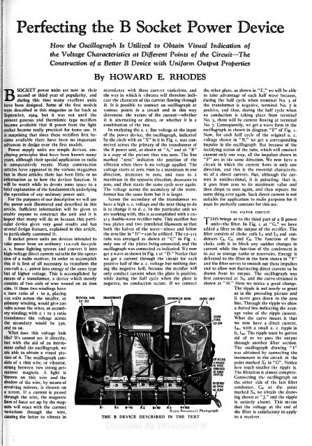
.manent1shadowPerfecting theHow the Oscillograph Is Utilized to Obtain Visual Indication ofthe Voltage Characteristics at Different Points of the CircuitTheConstruction of a Better B Device with Uniform Output PropertiesSOCKET power units are now in theirsecond or third year of popularity, andBy HOWARD E.RHODES;variations through the wire,causing the latter to vibrate in THEaccordance with these current variations, andthe way in which it vibrates will therefore indicateduring this time many excellent unitsthe character of the current flowing throughhave been designed. Some of the first models it. It is possible to connect an oscillograph atwere described in this magazine as far back as various points in a circuit and in this waySeptember, 1924, but it was not until the determine the nature of the current whetherpresent gaseous and thermionic type rectifiers it is alternating or direct, or whether it is abecame available that B power from the light combination of the two.socket became really practical for home use. It In analyzing the a. c. line voltage at the inputis surprising that since these rectifiers first becameof the power device, the oscillograph, indicatedavailable there have been no important by the circle with an "X" in it in Fig. I, was con-advances in design over the first models.nected across the primary of the transformer ofPower supply units are simple devices, employingthe B power unit, as shown at "A," and at "B"principles that have been known manyis a copy of the picture that was seen. The lineyears, although their special application to radio marked "zero" indicates the position of theiscomparatively recent. Many construction vibrator when there is no voltage applied. Thearticles have appeared in the various magazines voltage starts at zero, rises to a maximum in onebut in these articles there has been little or no direction, decreases to zero, and rises to ainformation as to how the devices function. It maximum in the opposite direction, decreases towill be worth while to devote some space to a zero, and then starts the same cycle over again.brief explanation of the fundamentals underlying The voltage across the secondary of the transformerthe operation of any ordinary power unit.has the same form but it is larger.the For the purposes of our description we will use Across the secondary of the transformer wethe power unit illustrated and described in this have a high a. c. voltage and the next thing to doarticle. Sufficient information will be given to is to change it to d. c. In the particular unit weenable anyone to construct the unit and it is are working with, this isaccomplished with a cxhopedthat many will do so because this particular3 1 3 double-wave rectifier tube. This rectifier hasdevice gives very good results and has two plates and two paralleled filaments so thatseveral design features, explained in this article, both the halves of the wave above and belowto particularly commend it.the zero line in " B" can be utilized. The cx-3 13B socket power units are devices intended to tube was arranged as shown at "C" in Fig. i,take power from an ordinary lo-volt 6o-cycle only one of the i plates being connected, and thea. c. house lighting system and convert it into oscillograph was connected as indicated. We nowhigh-voltage direct current suitable for the operationof a radio receiver. In order to accomplish we get a current through the circuit for eachget a wave as shown in Fig. at " D." Notice thatithis it is first of all necessary to transform the positive half of the a. c. voltage but nothing duringI io-vo!t a. c.power into energy of the same typethe negative half, because the rectifier willbut of higher voltage. This is accomplished by only conduct current when the plate is positive,means of a transformer, a device which merely while during the half cycle when the plate isconsists of two coils of wire wound on an iron negative, no conduction occurs. If we connectcore. If these two windings havea turn ratio of i to 2, placing1 10 volts across the smaller, orTUICCONDENSER BANI\RECTIFIERprimary winding, would give 220CX-313volts across the other, or secondarywinding; with a i to 3 ratiotransformer the voltage acrossthe secondary would be 330,and so on.What does this voltage looklike? We cannot see it directly,but with the aid of an instrumentcalled the oscillograph, weare able to obtain a visual pictureof it. The oscillograph consistsof a thin wire, or vibrator,strung between two strong permagnets.A light is'thrown on this wire and theof the wire, by means ofrevolving mirrors, is thrown on'a screen. If a current is passedthrough the wire, the magneticlines of force set up by the magnetswillIreact with the currentthe other plate, as shown in " E," we will be ableto take advantage of each half wave because,during the half cycle when terminal No. 5 ofthe transformer is negative, terminal No. 7 ispositive, and thus, during the half cycle whenno conduction is taking place from terminalNo. 5, there will be current flowing at terminalNo. 7. Consequently, we get a wave form in theoscillograph as shown in diagram "F" of Fig. I.Now, for each half cycle of the original a. c.voltage shown in" B," we get a correspondingimpulse in the oscillograph. But because of therectifying action of the tube, which will conductcurrent only one way, all the impulses shown in"F" are in the same direction. We now have acircuit in which the current flows in only onedirection, and this is the essential characteristicof a direct current. But, althoughCHOKE UNITLthe currentis unidirectional, it is pulsating; that is,itgoes from zero to its maximum value andthen drops to zero again, and then repeats thesame thing over again. Such direct current is notsuitable for application to radio purposes for itmust be perfectly constant for this use.THE FILTER CIRCUITTHIS brings us to the third part of a B powerunit the filter. In Fig. i, at "G," we haveadded a filter to the output of the rectifier. Thefilter consists of choke coils Li and Lj and condensersCi, d, and Ca. The function of thechoke coils is to block any sudden changes incurrent while the function of the condensers isto act as storage tanks or reservoirs. Energy isdelivered to the filter in the form shown in "F"and the filter serves to smooth out these impulsesand to allow non fluctuating direct current to bedrawn from its output. The oscillograph wasfirst connected at Xi, and the curve obtained isshown at "H." Here we notice a great change.The ripple is not nearly as greatas in the preceding picture andit never goes down to the zeroline. Through the ripple we showa dotted line indicating the averagevalue of the ripple current.What the curve means is thatwe now have a direct current,ADCAST PhotographTEXTIdci with a small a. c. ripple init, lac. The ripple must be gottenrid of so we pass the outputthrough another filter section.The oscillograph drawing "I"was obtained by connecting theinstrument in the circuit at thepoint marked \2 in "G". Noticehow much smaller the ripple is.The filtration is almost complete.Connecting the oscillograph onthe other side of the last filtercondenser, Ca, at the pointmarked Xj, we obtain the drawingshown at "J," and the rippleis entirely absent. This meansthat the voltage at the end ofthe filter is satisfactory to applyto a receiver.


