38 RADIO BROADCAST MAY, <strong>1927</strong>Interest to All DX Fans." Only one paragraphneed be lifted :The inventor's claims regarding the applicationof polarized harmonics was (sic) a little toodeep for the writer but to demonstrate what hemeant he tuned in KYW where Mr. Meehan wassinging an Indian song and by manipulation ofthe loop he entirely eliminated the accompaniment,also reversing the situation by bringing theaccompaniment up so loud that it interferedwith the singer. Another demonstration on anorchestra was the elimination or making ofthe string instruments predominate at will.On a mixed duet the soprano could be almostcompletely tuned out leaving the tenor singerpredominating and vice versa. Altogether, thedemonstration was very remarkable.The only commentbet!"Ican think of is: "YouThe <strong>Radio</strong> Club of Americaone evening each month, in the largelecture room of Havemeyer Hall, at ColumbiaUniversity, the portrait of the vener-FORable James Renwick,LL. D., Professor ofNatural Philosophyand Chemistry, 1820-1854, looks down on agroup of young men,and some older ones,gathered to discuss asubject which did notexist during his life.There are a hundredof these young men,more or less. They talkabout power packs,loud speakers, shortwavetransmitters,tendencies in modernradio receivers. Theportraitof ProfessorRenwick, who livedwhile Clerk Maxwellwas evolving theelectro -magneticseems to bear atheory,slightly puzzled frown.Seated at the table, from left to right: George H. Clark, E. E. Bucher,But the members ofGano Dunn, Edwin H. Armstrong, Michael I.Pupin, E. V. Amy, George J.the <strong>Radio</strong> Club ofEltz, Jr., David Sarnoff, George Burghard, John L. Hogan, Paul F. GodleyAmerica never look upat him. He is too far back for them. Theirthe members of the Club werethoughts sometimes regress to the early days ofradio, to the year 1909, say, when the Club wasfounded. In radio that is a long time. <strong>Radio</strong> menthink mainly in the present; they find plentythere to occupy them.The Club has two principal objects oneconcerned with the engineering aspects of theradio art, the other with the perpetuation ofthe amateur tradition. The Year Book for 1926states: "The Club now has among its membersmany prominent scientists, inventors, and engineers,as a glance at the membership list willshow. However, it is always anxious to embraceamateurs of the present day, in order that itsmembership shall never lack the renewed lifegiven by embryo scientists." It is primarily anamateur association, as the Institute of <strong>Radio</strong>Engineers is fundamentally a professional body.Amateurs and professionals belong to both organizations,but the <strong>Radio</strong> Club members neverforget that they were or are radio amateurs,while the members of the I. R. E., carrying theburden of radio scholarship, seldom forget thatthey are professionals.The Club now has some 400 members, ofwhom 108 are of Fellow grade. Fellows qualifyby five years of membership in the Club or bycontributions to the radio art, at the discretionof the Board of Directors, the governing body.It consists of a President, Vice-President,Treasurer, Corresponding Secretary, RecordingSecretary, and thirteen Directors. The officersand seven Directors are elected annually by themembership; the remaining six Directors areelected by a majority vote of the newly constitutedBoard of Direction at its first meeting.This year, the President of the Club is Ernest V.Amy; C. R. Runyon, Jr. is Vice-President. PastPresidents are W. E. D. Stokes, Jr., Frank King,George J. Eltz, Jr., Edwin H. Armstrong (1916-1920), and George E. Burghard (1921-1925).Mr. Amy was re-elected in 1926 for the presentyear.Among the authors who have presented papersbefore the <strong>Radio</strong> Club of America are includedArmstrong, Farrand, Van Dyck, Weagant,Hazeltine, W. C. White, Godley, Conrad,Heising, Aceves, Clement, Morecroft, Grebe,John Stone Stone, Lowenstein, Dubilier, Goldsmith,Marriott, Logwood, Pacent, and Hogan.The completelist is a formidable one, and thenames above represent it only partially. AsAT A RADIO CLUB BANQUETThe <strong>Radio</strong> Club of America has the name. It is agoing concern. It has a membership of 400 at thiswriting. An inspection of the 1926 Year Bookreveals that 78 per cent, of the members thereinlisted reside in New York City or its suburbs.But it is not a club, as yet. It maintains an officeat 55 West 42nd Street, New York City, but ithas no lounging rooms where the members canguzzle bottles of cool ginger ale, boast abouttheir distance records of fifteen years ago, recallfondly the days when Doc. Hudson called FNKwith a service on 600 meters to remind John V. L.Hogan that he had left his pipe at the Doctor'shouse the night before, and consummate milliondollar deals. If half the present membershipwanted a club, it could be started on a modestthis year or next. Such a development, ofscale,course, would not interfere with the monthlytechnical sessions, and technical membershipon the present order, with dues of $3 and $5 ayear, could be retained for those not interestedin the proposed aspect of the Club's activities.No one who has attended meetings of the Club,or been entertained at one of its annual banquets,can doubt that the organization has the vitalityand energy necessaryto take the lead in thisenterprise. Steps havealready been taken inthis direction. It is interestingto note thatthe Club has recentlyappointed a special" House Committee"for the purpose of investigatingthe desirabilityof such anunderstanding and tosubmit recommendationsfor organizationand financing. A modestClub House, withcomfortable loungingroom or rooms, isplanned. The radiomen in and aroundNew York will awaitdevelopments withmuch interest, nowthat the wheels haveactually begun toturn.permanent quarters, is obviously within reach. may be designed and calibrated to measure tele-early as 1912 Technical Operation of <strong>Broadcast</strong>ingsquare-law variable condensersand directional radio transmission. The value oftalking about Stationsthe papers presented, to the radio art as a whole,75. Volume Indicatorshas been inestimable. They form a contributionto the engineering literature second only to the 1HE collected Proceedings of the Institute of <strong>Radio</strong>Engineers. Incidentally, these papers are printedTsight of a milliammeter in the platecircuit of an overloaded tube, its needlefluctuating violently, is familiar to everyin RADIO BROADCAST.broadcast operator and engineer. When the tubeThe discussions following the presentation of is in the speech circuits of the transmitter thepapers are lively and informal. Nobody tries to sight, for obvious reasons, is a deplorable one,display his knowledge and no one is afraid to but the principle, or something on its order, isshow his ignorance. The attitude issimply that valuable for preventing the very overloadingof a group of men vastly interested in radio, which the fluctuating milliammeter shows. Thiswhether or not they are making any money out is when it is embodied in the instrument calledof it, who meet once a month to talk about the "volume indicator," much used in broadcastingthe subject which happens to entertain themas a visual guide in setting energymost.levels.And now, what course is to be charted for the Before going into the description of one typefuture? Will the Club remain a sort of junior of volume indicator I should like to make itengineering society, or will it become a club clear that it is an indicator, as the name implies,literally? One plausible guess is that the organizationrather than a measuring instrument. Basically,will become a club in fact as well as the instrument is an alternating current volt-in name, within the next few years, but without meter, and in certain forms it may be calibratedsacrificing its technical status. The two roles as an accurate low-reading instrument of thisare in no way incongruous. The formation of class, extremely useful in telephone and radiosome sort of radio club in New York City, with work for measuring audio potentials. Again, it
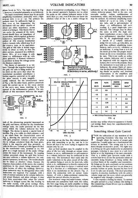
MAY, <strong>1927</strong>phone levels in TU's. The form shown in Fig.i, however, is intended primarily as an indicator.The input transformer shown may be an audioamplifying transformer, preferably with a highstep-upratio (1:10 or 1:5). The primary impedancemust be sufficiently high sothat, even at low frequencies, theinstrument will not affect circuits ofabout 500 ohms impedance, acrosswhich it is bridged. This means that at100 cycles the primary of the transformershould have an impedanceInputof20,000 ohms, which requires 40 henrysinductance, approximately. The secondaryof this step-up transformerfeeds a vacuum tube, which may be ofthe UX20I-A type, or its equivalent.The grid of this tube is biased negativelyto about 10 volts, so that theplate current, measured on a milliammeter,MA., of o-io range, is onlyabout 0.5 milliampere with 90 voltsplate potential. A filament voltmeteris provided to keep the voltage acrossthe filament constant.The theory of operationis as follows:Through the negative biasing ofthe grid, the tube is being worked sofar down on the curve that when thetransformer secondary contributes afurther negative potential to the gridInputthe plate current is only insignificantlyreduced. See the characteristic curveof Fig. 3. On the other hand, positive potentialscarry the current up on to the steep portionof the curve once more, resulting in a flickupward of the milliammeter pointer. The amplitudeof this movement indicates the magni-VOLUME INDICATORSshort of transmitter overloading, is 5.0. Then itis the control operator's business not to allowhis peaks on the volume indicator meter to hitmore than 5.0, and, even if he does not know theabsolute value of the r. m. s. audio voltage heFIG.STATIC CHARACTERISTICUX-201 -A90 V. PlateImfd.Reacta nee (Am plifyingTransformer with Primary& Secondary in series, additively )sufficiently on the second tube, which is thevolume indicator proper. Both in the one- andtwo-tube outfits, various combinations oftransformers, tubes, and indicating instrumentsmay be utilized. An ordinary amplifying transformerof i :3 or i .-5 ratio, a highmutube, and a galvanometer ofabout 1.5 milliamperes full scalereading, is a good single-tube combination.The voltages may be aboutthe same as with the high ratioinput transformer, ux-2oi-A tube, ando-io milliammeter described below.Mr. W. K. Aughenbaugh sends ina sketch of a volume indicatorusing two ux-i I2's, 45 volts plate, noGRIDVOLTSgrid bias, ordinary amplifying transformers,and a o-io d.c. voltmeter asan indicator. A swing from 2 to 6 onthe meter gives him the proper modulationon the WFBG transmitter, whichhe runs. This is not really an orthodoxvolume indicator, and it wouldbe improved with the negative biasfeature, but it serves the purpose. Sincethe instrument is used only as a leve'indicator, the proper limits of operationhaving been established by listeningchecks on quality and overloadobservations in the amplifiers andtransmitter, the operators at eachMA. D.C.0-10 =; .Milliamperes s90V.3FIG. 2tude of the alternating potential impressed onthe grid, and hence, divided by the transformervoltage ratio, the audio potential on the lineacross which the volume indicator has beenbridged. The device ismerely a special form ofrectifier. Fig. 4 is a table, in which columns i and2 are taken from the characteristic curve ofFig. 3, showing the variation of plate currentwith grid potential. Column 3 shows the plusrise in voltage calculated from the base point,which is the negative grid bias potential, 10volts in this case. Column 4is this figure dividedbythe transformer ratio, assumed as 10; thisgives us a rough measure of the audio voltageacross the input of the instrument. By tappingvarious potentials along the grid bias batteryone may calibrate a volume indicator, for comparativepurposes, in this way. The results shouldnot be taken as absolute values, because theresponse characteristic of the meter, the terminalconditions in the circuit being measured, andother factors, all affect the readings. However,these unknowns may be disregarded when onlyindications are required. For example, with atube of normal emission in the volume indicator,and proper filament and plate voltages, it mayhave been ascertained that, when the volumeindicator isbridged across the line leading tothe radio station, with given settings there,the maximum allowable deflection of the meter,
- Page 1 and 2: RADIO BROADCASTVOLUME XIMAY, 1927,
- Page 3 and 4: INDEX.ContinuedPAGEThreshold of Hea
- Page 5 and 6: RADIO BROADCAST ADVERTISERALUMINUMB
- Page 7 and 8: RADIO BROADCAST ADVERTISERfIA REALA
- Page 9 and 10: :RADIO BROADCASTVOLUME XI NUMBER 1M
- Page 11 and 12: MAY, 1927WITH MACMILLAN TO THE ARCT
- Page 13: THE MARCHInterpretation of Current
- Page 16 and 17: 18volved the law in precarious lega
- Page 18 and 19: The ElectricalA Non-Technical Expla
- Page 20 and 21: 22 RADIO BROADCAST MAY, 1927type of
- Page 22 and 23: A Balanced Short-Wave ReceiverA Des
- Page 24 and 25: What About the A BatteryThe Importa
- Page 26 and 27: 28 RADIO BROADCAST MAY, 1927The cas
- Page 28 and 29: 30 RADIO BROADCAST MAY, 1927NO STRA
- Page 30 and 31: 32 RADIO BROADCAST MAY, 1927from th
- Page 32 and 33: 34 RADIO BROADCAST MAY, 1927the ave
- Page 34 and 35: AS THE BROADCASTER SEES ITDrawings
- Page 38 and 39: Some Facts About Coil DesignThe Osc
- Page 40 and 41: 42 RADIO BROADCAST MAY, 1927Shows e
- Page 42 and 43: 44 RADIO BROADCAST MAY. 1927The fil
- Page 44 and 45: ''Measuring TubeCharacteristicsA Pa
- Page 46 and 47: 48 RADIO BROADCAST MAY, 1927MUTUAL
- Page 48 and 49: 50 RADIO BROADCAST MAY, 1927whose b
- Page 50 and 51: RADIO BROADCAST ADVERTISERThe Radio
- Page 52 and 53: 54 RADIO BROADCAST ADVERTISERA Bett
- Page 54 and 55: 56 RADIO BROADCAST ADVERTISERNo. 94
- Page 56 and 57: .58 RADIO BROADCAST ADVERTISERTJour
- Page 58 and 59: 60 RADIO BROADCAST ADVERTISERMire's
- Page 60 and 61: ''. ..RADIO BROADCAST ADVERTISERin