

Radio Broadcast - 1927, May - 61 Pages, 4.9 MB ... - VacuumTubeEra
Radio Broadcast - 1927, May - 61 Pages, 4.9 MB ... - VacuumTubeEra
Radio Broadcast - 1927, May - 61 Pages, 4.9 MB ... - VacuumTubeEra

Create successful ePaper yourself
Turn your PDF publications into a flip-book with our unique Google optimized e-Paper software.
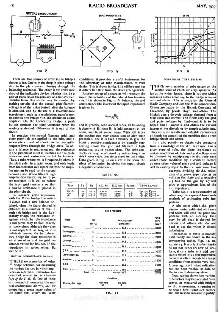
48 RADIO BROADCAST MAY, <strong>1927</strong>MUTUAL CONDUCTANCEINPUT CONDUCTANCEFIG. 8FIG. 9There arc two sources of error in the bridgesshown so far. One is in the drop in plate voltagedue to the plate current flowing through thebalancing resistance. The other is the resistancedrop of the indicating device, whether this be apair of receivers or the primary of a transformer.Trouble from this source may be avoided bymaking certain that the actual plate-filamentvoltage is of the value desired after the balanceis obtained, and by the use of a low-resistancetransformer, such as a modulation transformer,to connect the bridge with the associated audioamplifier. On the Laboratory bridge, a pushbutton connects the plate voltmeter when itsreading is desired. Otherwise it is out of thecircuit.In practice, the normal filament, grid, andplate potentials are appliedto the tube, and alooo-cycle current of about one to two milliamperesflows through the bridge arms. To obtaina balance in measuring mu, the resistancein the grid circuit is set at 10 ohms and the plateresistance and variometer varied for balance.Thus, a tube whose mu is 8 requires 80 ohms inthe plate side. In a quiet room, and with leadsfrom the oscillator well separated from the amplifiermu can be read to the seconddecimal place. When tubes of highamplification factor, say 20 to 30,are measured, it is well to reducethe input grid resistance so thata smaller resistance is placed inTypeconditions, itprovides a useful instrument forthe laboratory or tube manufacturer, or evendealer. This is shown in Fig. 8. It will be seen thatit differs but little from the other arrangements.Another set-up of apparatus will measure theinput characteristics of the tube at low frequencies.It is shown in Fig. 9. At balance, the gridconductance (the inverse of the input impedance}isgiven by:RiRi R,and in practice, with normal tubes, all balancingis done with RI, since R2 is held constant at 100ohms, and Rs at 10,000 ohms. With soft tubesthe conductance may change sign at high platepotentials, and it is then necessary to give theinput a positive conductance by actually connectingacross the grid and filament a highresistance, say of 50,000 ohms. The tube conductancemay be obtained by subtracting fromthis known value, that determined by the bridge.Data given in Fig. 10 on a soft tube show theeffect of ionization in giving the input circuita negative conductance.TABLE NO.Ithe plate circuit.To measure plate impedancewith the Miller bridge, the switchis closed and a new balance obtained,when the factor desired isobtained as a function of mu. Inboth this bridge and in the Laboratorybridge, the resistance, R,against which the tube impedanceiscompared, may be fixed exactlyat 10,000 ohms, although the valueas it isis not important as longdefinitely known. On the Laboratorybridge the plate resistance isset at 100 ohms and the grid resistancevaried for balance. If theimpedance is 12,000 ohms, R Kwill be 120.MUTUAL CONDUCTANCE BR1DGRIPHEREare a number of other*bridge schemes for measuringthe various factors in which engineersare interested. Ballantine hasdescribed several in the Proceedingsof the I. R. E. One of theseis a method of measuring the mutualconductance di*"""""/, and forcomparing a great many tubes ofthe same sort under the same


