

Radio Broadcast - 1927, May - 61 Pages, 4.9 MB ... - VacuumTubeEra
Radio Broadcast - 1927, May - 61 Pages, 4.9 MB ... - VacuumTubeEra
Radio Broadcast - 1927, May - 61 Pages, 4.9 MB ... - VacuumTubeEra

You also want an ePaper? Increase the reach of your titles
YUMPU automatically turns print PDFs into web optimized ePapers that Google loves.
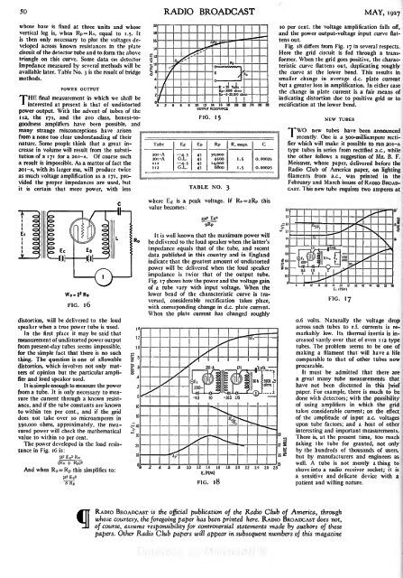
50 RADIO BROADCAST MAY, <strong>1927</strong>whose base is fixed at three units and whosevertical leg is, when R P= Ro, equal to 1.5. Itis then only necessary to plot the voltages developedacross known resistances in the platecircuit of the detector tube and to form the abovetriangle on this curve. Some data on detectorimpedance measured by several methods will beavailable later. Table No. 3 is the result of bridgemethods.TpHEPOWER OUTPUTfinal measurement in which we shall be* interested at present is that of undistortedpower output. With the advent of tubes of the112, the 171, and the 210 class, honest-togoodnessamplifiers have been possible, andmany strange misconceptions have arisenfrom a none too clear understanding of theirnature. Some people think that a great increasein volume will result from the substitutionof a 171 for a 20I-A. Of course sucha result is impossible. As a matter of fact the201 A, with its larger mu, will produce twiceas much voltage amplification as a 171,providedthe proper impedances are used, butit is certain that more power, with lessTube10 12 14 16 18 20OUTPUT RESISTANCEFIG. 15distortion, will be delivered to the loudspeaker when a true power tube is used.In the first place it may be said thatmeasurement of undistorted power outputfrom present-day tubes seems impossible,for the simple fact that there is no suchthing. The question is one of allowabledistortion, which involves not only mattersof opinion but the particular amplifierand loud speaker used.It is simple enough to measure the powerfrom a tube. It isonly necessary to measurethe current through a known resistance,and if the tube constants are knownto within ten per cent., and if the griddoes not take over 10 microamperes in350,000 ohms, approximately, the measuredpower will check the mathematicalvalue to within 10 per cent.The power developed in the load resistancein Fig.1 6 is:(tfEg' Ro(Ro + Rp)*And when R = R p this simplifies to:


