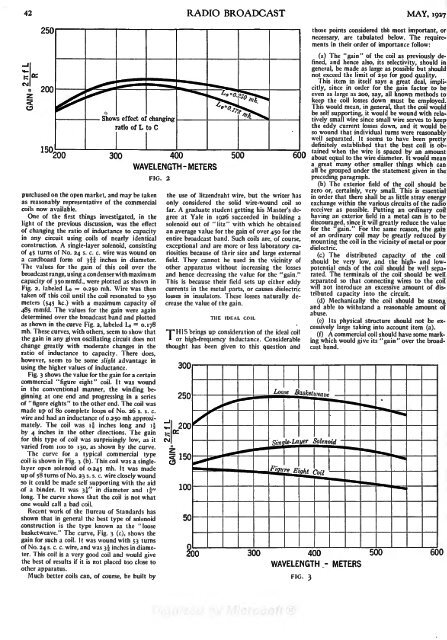
42 RADIO BROADCAST MAY, <strong>1927</strong>Shows effect of changingratio of L to C150200 300 400WAVELENGTH -METERSFIG. 2purchased on the open market, and may be takenas reasonably representative of the commercialcoils now available.One of the first things investigated, in thelight of the previous discussion, was the effectof changing the ratio of inductance to capacityin any circuit using coils of nearly identicalconstruction. A single-layer solenoid, consistingof 45 turns of No. 24s. c. c. wire was wound ona cardboard form of 3!! inches in diameter.The values for the gain of this coil over thebroadcast range, using a condenser with maximumcapacity of 35ommfd., were plotted as shown inFig. 2, labeled I_o= 0.250 mh. Wire was thentaken off this coil until the coil resonated to 550meters (545 kc.) with a maximum capacity of485 mmfd. The values for the gain were againdetermined over the broadcast band and plottedas shown in the curve Fig. 2, labeled = Lo 0.178mh. These curves, with others, seem to show thatthe gain in any given oscillating circuit does notchange greatly with moderate changes in theratio of inductance to capacity. There does,however, seem to be some slight advantage inusing the higher values of inductance.Fig. 3 shows the value for the gain for a certaincommercial "figure eight" coil. It was woundin the conventional manner, the winding beginningat one end and progressing in a seriesof "figure eights" to the other end. The coil wasmade up of 80 complete loops of No. 26 s. s. c.wire and had an inductance of 0.250 mh approximately.The coil was if inches long and ifby 4 inches in the other directions. The gainfor this type of coil was surprisingly low, as itvaried from 100 to 130, as shown by the curve.The curve for a typical commercial typecoil is shown in Fig. 3 (b). This coil was a singlelayeropen solenoid of 0.245 mh. It was madeup of 58 turns of No. 23 s. s. c. wire closely woundso it could be made self supporting with the aidof a binder. It was 3!" in diameter and if"long. The curve shows that the coil is not whatone would call a bad coil.Recent work of the Bureau of Standards hasshown that in general the best type of solenoidconstruction is the type known as the "loosebasketweave." The curve, Fig. 3 (c), shows thegain for such a coil. It was wound with 53 turnsof No. 24s. c. c. wire, and was 35 inches in diameter.This coil is a very good coil and would givethe best of results if it is not placed too close toother apparatus.Much better coils can, of course, be built by500 600the use of litzendraht wire, but the writer hasonly considered the solid wire-wound coil sofar. A graduate student getting his Master's degreeat Yale in 1926 succeeded in building asolenoid out of "litz" with which he obtainedan average value for the gain of over 450 for theentire broadcast band. Such coils are, of course,exceptional and are more or less laboratory curiositiesbecause of their size and large externalfield. They cannot be used in the vicinity ofother apparatus without increasing the lossesand hence decreasing the value for the "gain."This is because their field sets up either eddycurrents in the metal parts, or causes dielectriclosses in insulators. These losses naturally decreasethe value of the gain.THE IDEAL COILTHIS brings up consideration of the ideal coilor high-frequency inductance. Considerablethought has been given to this question andthose points consideredthe most important, ornecessary, are tabulated below. The requirementsin their order of importance follow:(a) The "gain" of the coil as previously defined,and hence also, its selectivity, should ingeneral, be made as large as possible but shouldnot exceed the limit of 250 for good quality.This item in itself says a great deal, implicitly,since in order for the gain factor to beeven as large as 200, say, all known methods tokeep the coil losses down must be employed.This would mean, in general, that the coil wouldbe self supporting, it would be wound with relativelysmall wire since small wire serves to keepthe eddy current losses down, and it would beso wound that individual turns were reasonablywell separated. It seems to have been prettydefinitely established that the best coil is obtainedwhen the wire is spaced by an amountabout equal to the wire diameter. It would meana great many other smaller things which canall be grouped under the statement given in thepreceding paragraph.(b) The exterior field of the coil should bezero or, certainly, very small. This is essentialin order that there shall be as little stray energyexchange within the various circuits of the radioreceiver as possible. Putting an ordinary coilhaving an exterior field in a metal can is to bediscouraged, since it will greatly reduce the valuefor the "gain." For the same reason, the gainof an ordinary coil may be greatly reduced bymounting the coil in the vicinity of metal or poordielectric.(c) The distributed capacity of the coilshould be very low, and the high- and lowpotentialends of the coil should be well separated.The terminals of the coil should be wellseparated so that connecting wires to the coilwill not introduce an excessive amount of distributedcapacity into the circuit.(d) Mechanically the coil should be strongand able to withstand a reasonable amount ofabuse.(e) Its physical structure should not be excessivelylarge taking into account item (a).(f) A commercial coil should have some markingwhich would give its "gain" over the broadcastband.200 300 400500 600WAVELENGTH - METERSFIG. 3
.manent1shadowPerfecting theHow the Oscillograph Is Utilized to Obtain Visual Indication ofthe Voltage Characteristics at Different Points of the CircuitTheConstruction of a Better B Device with Uniform Output PropertiesSOCKET power units are now in theirsecond or third year of popularity, andBy HOWARD E.RHODES;variations through the wire,causing the latter to vibrate in THEaccordance with these current variations, andthe way in which it vibrates will therefore indicateduring this time many excellent unitsthe character of the current flowing throughhave been designed. Some of the first models it. It is possible to connect an oscillograph atwere described in this magazine as far back as various points in a circuit and in this waySeptember, 1924, but it was not until the determine the nature of the current whetherpresent gaseous and thermionic type rectifiers it is alternating or direct, or whether it is abecame available that B power from the light combination of the two.socket became really practical for home use. It In analyzing the a. c. line voltage at the inputis surprising that since these rectifiers first becameof the power device, the oscillograph, indicatedavailable there have been no important by the circle with an "X" in it in Fig. I, was con-advances in design over the first models.nected across the primary of the transformer ofPower supply units are simple devices, employingthe B power unit, as shown at "A," and at "B"principles that have been known manyis a copy of the picture that was seen. The lineyears, although their special application to radio marked "zero" indicates the position of theiscomparatively recent. Many construction vibrator when there is no voltage applied. Thearticles have appeared in the various magazines voltage starts at zero, rises to a maximum in onebut in these articles there has been little or no direction, decreases to zero, and rises to ainformation as to how the devices function. It maximum in the opposite direction, decreases towill be worth while to devote some space to a zero, and then starts the same cycle over again.brief explanation of the fundamentals underlying The voltage across the secondary of the transformerthe operation of any ordinary power unit.has the same form but it is larger.the For the purposes of our description we will use Across the secondary of the transformer wethe power unit illustrated and described in this have a high a. c. voltage and the next thing to doarticle. Sufficient information will be given to is to change it to d. c. In the particular unit weenable anyone to construct the unit and it is are working with, this isaccomplished with a cxhopedthat many will do so because this particular3 1 3 double-wave rectifier tube. This rectifier hasdevice gives very good results and has two plates and two paralleled filaments so thatseveral design features, explained in this article, both the halves of the wave above and belowto particularly commend it.the zero line in " B" can be utilized. The cx-3 13B socket power units are devices intended to tube was arranged as shown at "C" in Fig. i,take power from an ordinary lo-volt 6o-cycle only one of the i plates being connected, and thea. c. house lighting system and convert it into oscillograph was connected as indicated. We nowhigh-voltage direct current suitable for the operationof a radio receiver. In order to accomplish we get a current through the circuit for eachget a wave as shown in Fig. at " D." Notice thatithis it is first of all necessary to transform the positive half of the a. c. voltage but nothing duringI io-vo!t a. c.power into energy of the same typethe negative half, because the rectifier willbut of higher voltage. This is accomplished by only conduct current when the plate is positive,means of a transformer, a device which merely while during the half cycle when the plate isconsists of two coils of wire wound on an iron negative, no conduction occurs. If we connectcore. If these two windings havea turn ratio of i to 2, placing1 10 volts across the smaller, orTUICCONDENSER BANI\RECTIFIERprimary winding, would give 220CX-313volts across the other, or secondarywinding; with a i to 3 ratiotransformer the voltage acrossthe secondary would be 330,and so on.What does this voltage looklike? We cannot see it directly,but with the aid of an instrumentcalled the oscillograph, weare able to obtain a visual pictureof it. The oscillograph consistsof a thin wire, or vibrator,strung between two strong permagnets.A light is'thrown on this wire and theof the wire, by means ofrevolving mirrors, is thrown on'a screen. If a current is passedthrough the wire, the magneticlines of force set up by the magnetswillIreact with the currentthe other plate, as shown in " E," we will be ableto take advantage of each half wave because,during the half cycle when terminal No. 5 ofthe transformer is negative, terminal No. 7 ispositive, and thus, during the half cycle whenno conduction is taking place from terminalNo. 5, there will be current flowing at terminalNo. 7. Consequently, we get a wave form in theoscillograph as shown in diagram "F" of Fig. I.Now, for each half cycle of the original a. c.voltage shown in" B," we get a correspondingimpulse in the oscillograph. But because of therectifying action of the tube, which will conductcurrent only one way, all the impulses shown in"F" are in the same direction. We now have acircuit in which the current flows in only onedirection, and this is the essential characteristicof a direct current. But, althoughCHOKE UNITLthe currentis unidirectional, it is pulsating; that is,itgoes from zero to its maximum value andthen drops to zero again, and then repeats thesame thing over again. Such direct current is notsuitable for application to radio purposes for itmust be perfectly constant for this use.THE FILTER CIRCUITTHIS brings us to the third part of a B powerunit the filter. In Fig. i, at "G," we haveadded a filter to the output of the rectifier. Thefilter consists of choke coils Li and Lj and condensersCi, d, and Ca. The function of thechoke coils is to block any sudden changes incurrent while the function of the condensers isto act as storage tanks or reservoirs. Energy isdelivered to the filter in the form shown in "F"and the filter serves to smooth out these impulsesand to allow non fluctuating direct current to bedrawn from its output. The oscillograph wasfirst connected at Xi, and the curve obtained isshown at "H." Here we notice a great change.The ripple is not nearly as greatas in the preceding picture andit never goes down to the zeroline. Through the ripple we showa dotted line indicating the averagevalue of the ripple current.What the curve means is thatwe now have a direct current,ADCAST PhotographTEXTIdci with a small a. c. ripple init, lac. The ripple must be gottenrid of so we pass the outputthrough another filter section.The oscillograph drawing "I"was obtained by connecting theinstrument in the circuit at thepoint marked \2 in "G". Noticehow much smaller the ripple is.The filtration is almost complete.Connecting the oscillograph onthe other side of the last filtercondenser, Ca, at the pointmarked Xj, we obtain the drawingshown at "J," and the rippleis entirely absent. This meansthat the voltage at the end ofthe filter is satisfactory to applyto a receiver.
- Page 1 and 2: RADIO BROADCASTVOLUME XIMAY, 1927,
- Page 3 and 4: INDEX.ContinuedPAGEThreshold of Hea
- Page 5 and 6: RADIO BROADCAST ADVERTISERALUMINUMB
- Page 7 and 8: RADIO BROADCAST ADVERTISERfIA REALA
- Page 9 and 10: :RADIO BROADCASTVOLUME XI NUMBER 1M
- Page 11 and 12: MAY, 1927WITH MACMILLAN TO THE ARCT
- Page 13: THE MARCHInterpretation of Current
- Page 16 and 17: 18volved the law in precarious lega
- Page 18 and 19: The ElectricalA Non-Technical Expla
- Page 20 and 21: 22 RADIO BROADCAST MAY, 1927type of
- Page 22 and 23: A Balanced Short-Wave ReceiverA Des
- Page 24 and 25: What About the A BatteryThe Importa
- Page 26 and 27: 28 RADIO BROADCAST MAY, 1927The cas
- Page 28 and 29: 30 RADIO BROADCAST MAY, 1927NO STRA
- Page 30 and 31: 32 RADIO BROADCAST MAY, 1927from th
- Page 32 and 33: 34 RADIO BROADCAST MAY, 1927the ave
- Page 34 and 35: AS THE BROADCASTER SEES ITDrawings
- Page 36 and 37: 38 RADIO BROADCAST MAY, 1927Interes
- Page 38 and 39: Some Facts About Coil DesignThe Osc
- Page 42 and 43: 44 RADIO BROADCAST MAY. 1927The fil
- Page 44 and 45: ''Measuring TubeCharacteristicsA Pa
- Page 46 and 47: 48 RADIO BROADCAST MAY, 1927MUTUAL
- Page 48 and 49: 50 RADIO BROADCAST MAY, 1927whose b
- Page 50 and 51: RADIO BROADCAST ADVERTISERThe Radio
- Page 52 and 53: 54 RADIO BROADCAST ADVERTISERA Bett
- Page 54 and 55: 56 RADIO BROADCAST ADVERTISERNo. 94
- Page 56 and 57: .58 RADIO BROADCAST ADVERTISERTJour
- Page 58 and 59: 60 RADIO BROADCAST ADVERTISERMire's
- Page 60 and 61: ''. ..RADIO BROADCAST ADVERTISERin