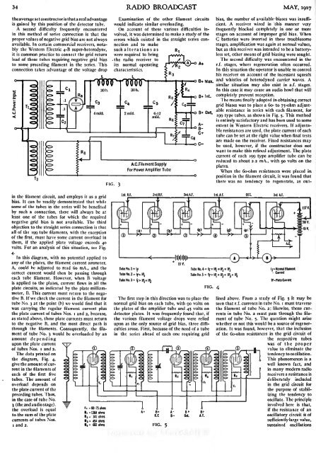
34 RADIO BROADCAST MAY, <strong>1927</strong>the average set constructor is that a real advantage Examination of the other filament circuits bias, the number of available biases was insufficient.A receiver wired in this manner veryisgained by this position of the detector tube. would indicate similar overloading.A second difficulty frequently encountered On account of these various difficulties involved,frequently blocked completely in one or morea study of the stages on account of improper grid bias. Whenin this method of series connection is that theproper values of negative grid bias are not always errors which existed in the straight series connectionand to makestages, amplification was again at normal values,C batteries were inserted in these troublesomeavailable. In certain commercial receivers, notablythe Western Electric 4-6 super-heterodyne, such alterations asbut as this receiver was intended to be a batterylessset, other means of grid biasing were sought.it is common practice to connect the grid return were required to bringlead of those tubes requiring negative grid bias the radio receiver toThe second difficulty was encountered in theto some preceding filament in the series. This its normal operatingr.f. stages, where regeneration often occurred.connection takes advantage of the voltage dropIn this situation the operator is unable to controlhis receiver on account of the incessant squealso B+ Max.and whistles of heterodyned carrier waves. Asimilar situation may also exist in a.f. stages.In this case it may cause an audio howl that willB+ Int. completely prevent reception.The means^^finally adopted in obtaining correctgrid biases was to place a 60- to 75-ohm adjustableresistance in series with each-4-0 filament, for3+ Det.199 type tubes, as shown in Fig. 5.This methodentirely satisfactory and has been used to someextent in Western Electric receivers. If adjustableresistances are used, the plate current of eachtube can be set at the right value when final testsare made on the receiver. Fixed resistances maybe used, however, if the constructor does notwant to make this refined adjustment. The platecurrent of each 199 type amplifier tube can bereducedA.C. Filament to about 2.2 mA., with 90 volts on theSupplyplates.For Power Amplifier TubeWhen the 6o-ohm resistances were placed inposition in the filament circuit, it was found thatthere was noFIG. tendency to regenerate, as out-3in the filament circuit, and employsit as a gridbias. It can be readily demonstrated that whilesome of the tubes in the series will be benefitedby such a connection, there will always be atleast one of the tubes for which the requirednegative grid bias is not available. The thirdobjection to the straight series connection is thatall of the 199 tube filaments, with the exceptionof the first, must have some current overload inthem, if the applied plate voltage exceeds 40volts. For an analysis of this situation, see Fig.4-In this diagram, with no potential applied toany of the plates, the filament current ammeter,A, could be adjusted to read 60 mA., and thecorrect current would then be passing througheach tube filament. However, when B voltageis applied to the plates, current flows in all theplate circuits, as indicated by the plate milliammeter,B. This current must return to the negativeB. If we check the current in the filament fortube No. 3 at the point (b) we would find that itwas carrying the regular filament current plusthe plate current of tubes Nos. i and 2, because,as stated above, these plate currents must returnto the negative B, and the most direct path isthrough the filaments. Consequently, the filamentof tube No. 3 would be overloaded by anamount dependingupon the plate currentof tubes Nos. i and 2.The data printed onthe diagram, Fig. 4,give the amount of currentin the filaments ofeach of the first fivetubes. The amount ofoverload depends onthe plate current of thepreceding tubes. Thus,in the case of tubs No.3 (the 2nd audio stage).the overload isequalto the sum of the platecurrents of tubes Nos.i and 2.1st. R.F. 2ndR.F. 2nd.A.F. 1st. A.F. DET. 3rd. A.F.Tube No. 1 -IfTube No. 4- lj-t-IP,+IP2+ IP 3-Tube No. 2- Ip- IP,TubeNo.5- If-t+ IP -t IP 1P, 2 3Tube No. 3- lf tlP,+ IFIG. 4Ir* Normal FilamentCurrentIP. Plate CurrentThe first step in this direction was to place the lined above. From a study of Fig. 5 it may benormal grid bias on each tube, with 90 volts on seen that r.f. currents in tube No. i must traversethe plates of the amplifier tube and 45 volts on the filament of tube No. 2; likewise, those currentsin tube No. 2 must pass through the fila-detector plates. It was frequently found that, ifthe various filament voltage drops were relied ment of tube No. 5.The question might ariseupon as the only source of grid bias, three difficultiesarose. First, because of the need of a tube ation. It was found, however, that the inclusionwhether or not this would be a source of regener-in the series ahead of each one requiring grid of the 6o-ohm resistances in the grid circuit ofthe respective tubeswas of the propervalue to eliminate thetendency tooscillation.This phenomenon is awell known fact, andin many modern radioreceivers a resistance isdeliberately includedin the grid circuit forthe purpose of stabilizingthe tendency tooscillate. The principleinvolved here is that,if the resistance of anoscillatory circuit is ofsufficiently large value,sustained oscillations
MAY, <strong>1927</strong> FILAMENT LIGHTING FROM THE A. C. MAINS 35FIG. 6resistances6o-ohm resistor ahead of each amplifier tube forcannot be produced therein. Such a circuit is saidseries, including i. Wire all filaments in ato have a high decrement.grid bias, (see Fig. 5).2.When the series filament receiver had beenChoose the proper order of wiring the filaments,so that the detector is next to the B minusprovided with proper grid biasing, as described,or ground connection.it was found that its performance was at least3. Place shunt resistances across each filament,equal to that of a similar set with parallel filaments.as shown in Fig. 5.This particular receiver had two stagesof tuned r.f., detector, and three stages of The foregoing discussion is based upon a plateresistance-coupled a.f. amplification. Five ux- voltage of 90 volts on all amplifier tubes, so that199 tubes and one ux-i 12 power tube were used. large signal voltages may be applied without distortion.Under this condition it is necessary thatA filament battery of 36 volts was employedfeeding 60 mA. to the set. A plate battery of 157 a negative grid bias be obtained in some mannervolts delivered a total current of 22 mA.for these tubes, such as by the use of the 6o-ohmIf the results of Fig. 4 are now applied to theset in consideration, it is readily seen that thefilaments of all the 199 tubes in series, with theexception of tube No. i, will carry a currentwhich is in excess of 60 mA. The excessive currentin the last tube in the series may rise to a valuewhich is30 per cent, above the normal value.The actual current overloads may be computedby reference to the table on this page. In thistable, the overload figures are obtained by deducting6ofrom the filament-current figures givenin the second column of figures. These data arebased on the assumption that all tubes haveproper grid bias, that amplifier tubes are providedwith 90 volts on the plates, and that detectortubes have 45 volts on the plates. Thisarrangement will give a plate current in eachamplifier tube of approximately 2.2 mA., whilethat of the detector tubes will average i.o mA.A very simple and satisfactory method of reducingthe filament current overload is to shunta bypass resistance across each filament, asshown in Fig. 5.These resistances do not allhave the same values, and their proper size, for199 tubes, is determined as follows :-.R = IExcess Filament Current, Amperes.For example, the last tube in a 6-tube serieswas measured, and its filament current wasfound to be 71 mA. The excess filament currentis therefore 1 1mA.,oro.oi amperes. The correctIvalue of the bypass resistance is then equal to,. or 273 ohms.The table shows the correct values of bypassresistance to be used in various combinations of199 tubes.When the receiver has been provided withthe correct biasing resistances and filamentshunts, it is now ready to be connected up foruse. If the receiver is to be used in connectionwith an electric power supply device, it may benecessary to take additional precautions to prevent"motor-boating."For the present discussion, the following rulessummarize the procedure in laying out a seriesfilament receiver using 199 tubes:in series with each amplifier filament.It is entirely possible, however, to build a satisfactoryseries filament radio receiver withoutthe use of these 6o-ohm resistances, for use onmoderate volumes. In this case it is essentialthat the amplifier plate voltage shall not exceed50 volts, so that the average plate current willlie between 2.0 and 2.5 mA. This situation frequentlyprevails in radio-frequency stages wherethe signal voltage is low enough not to warrantthe use of a high negative grid bias, and also inresistance-coupled a.f. stages where the actualvoltage on the plates is frequently of the orderof 40 volts.In such cases as these a very simple proceduremay be followed that of connecting the gridreturn leads to the negative leg of the respectivefilaments, as shown in Fig. 6. It is, of course,apparent that the use of shunt resistors acrosseach filament isalways necessary, in order toprevent current overload. It will also be advisableto provide some means of stabilizing the r.f.amplifier, thus preventing the tendency to oscillation.The inclusion of the 6o-ohm biasing resistancesreduces this tendency to a very lowdegree, but without their use, difficulties are athand. A satisfactory means of overcoming thissituation is to bypass these r.f. currents througha o.i -i .o mfd. condenser shunted across each filament,as shown in Fig. 6. The use of these bypasscondensers insures complete control over thereceiver at all times and affords a greater possibilityof high-quality reproduction.
- Page 1 and 2: RADIO BROADCASTVOLUME XIMAY, 1927,
- Page 3 and 4: INDEX.ContinuedPAGEThreshold of Hea
- Page 5 and 6: RADIO BROADCAST ADVERTISERALUMINUMB
- Page 7 and 8: RADIO BROADCAST ADVERTISERfIA REALA
- Page 9 and 10: :RADIO BROADCASTVOLUME XI NUMBER 1M
- Page 11 and 12: MAY, 1927WITH MACMILLAN TO THE ARCT
- Page 13: THE MARCHInterpretation of Current
- Page 16 and 17: 18volved the law in precarious lega
- Page 18 and 19: The ElectricalA Non-Technical Expla
- Page 20 and 21: 22 RADIO BROADCAST MAY, 1927type of
- Page 22 and 23: A Balanced Short-Wave ReceiverA Des
- Page 24 and 25: What About the A BatteryThe Importa
- Page 26 and 27: 28 RADIO BROADCAST MAY, 1927The cas
- Page 28 and 29: 30 RADIO BROADCAST MAY, 1927NO STRA
- Page 30 and 31: 32 RADIO BROADCAST MAY, 1927from th
- Page 34 and 35: AS THE BROADCASTER SEES ITDrawings
- Page 36 and 37: 38 RADIO BROADCAST MAY, 1927Interes
- Page 38 and 39: Some Facts About Coil DesignThe Osc
- Page 40 and 41: 42 RADIO BROADCAST MAY, 1927Shows e
- Page 42 and 43: 44 RADIO BROADCAST MAY. 1927The fil
- Page 44 and 45: ''Measuring TubeCharacteristicsA Pa
- Page 46 and 47: 48 RADIO BROADCAST MAY, 1927MUTUAL
- Page 48 and 49: 50 RADIO BROADCAST MAY, 1927whose b
- Page 50 and 51: RADIO BROADCAST ADVERTISERThe Radio
- Page 52 and 53: 54 RADIO BROADCAST ADVERTISERA Bett
- Page 54 and 55: 56 RADIO BROADCAST ADVERTISERNo. 94
- Page 56 and 57: .58 RADIO BROADCAST ADVERTISERTJour
- Page 58 and 59: 60 RADIO BROADCAST ADVERTISERMire's
- Page 60 and 61: ''. ..RADIO BROADCAST ADVERTISERin